


2-10
Cisco UCS C210 Server Installation and Service Guide
OL-20887-02
Chapter
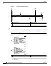
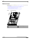
Step 2 Use the supplied KVM cable to connect a keyboard and VGA monitor to the console connector on the
front panel (see
Figure 1-1 on page 1-1).
Note Alternatively, you can use the VGA and USB ports on the rear panel. However, you cannot use the front
panel console connector VGA and the rear panel VGA at the same time. If you are connected to one VGA
connector and you then connect a video device to the other connector, the first VGA connector is
disabled. You can then reactivate the first VGA connector only by rebooting the server.
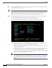
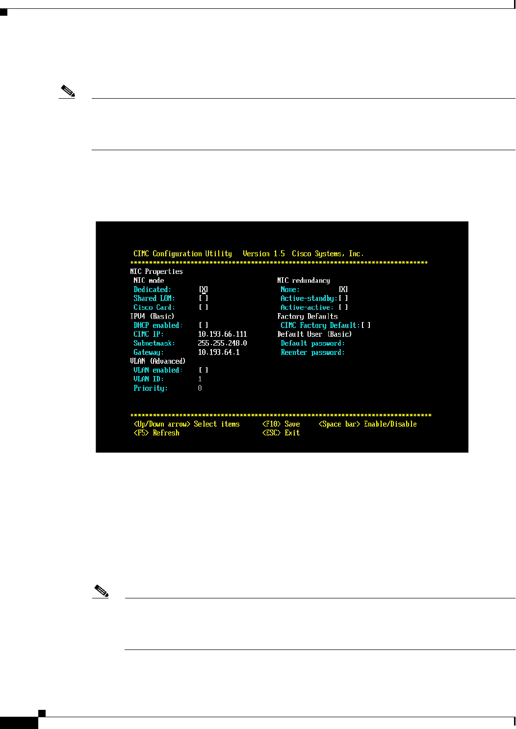
Step 3 Set NIC mode, NIC redundancy, and choose whether to enable DHCP or set static network settings:
a. Press the Power button to boot the server. Watch for the prompt to press F8.
b. During bootup, press F8 when prompted to open the BIOS CIMC Configuration Utility.
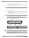
c. Set the NIC mode to your choice for which ports you want to use to access the CIMC for server
management (see
Figure 1-2 on page 1-2 for identification of the ports):
–
Dedicated—The 10/100 management port is used to access the CIMC. You have to select a NIC
redundancy and IP setting.
–
Shared LOM (default)—The two 1Gb Ethernet ports are used to access the CIMC. This is the
factory default setting, along with Active-active NIC redundancy and DHCP enabled.
–
Cisco Card—The ports on an installed Cisco network adapter card are used to access the CIMC.
You have to select a NIC redundancy and IP setting.
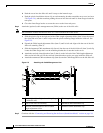
Note The Cisco Card NIC mode is currently supported only with a Cisco UCS P81E Virtual Interface
Card (N2XX-ACPCI01) that is installed in PCIe slot 1 (see
Figure 3-18 on page 3-34). See also
Special Considerations for the Cisco UCS P81E Virtual Interface Card (N2XX-ACPCI01),
page 3-37.