


3-41
Cisco UCS C210 Server Installation and Service Guide
OL-20887-02
Chapter
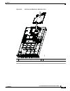
Replacing a SAS Extender or SAS Expander Card
To replace a SAS extender or SAS expander, follow these steps:
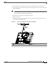
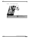
Step 1 Remove a SAS extender or SAS expander card:
a. Power off the server as described in the “Shutting Down and Powering Off the Server” section on
page 3-8.
b. Disconnect all power cords from the power supplies.
c. Slide the server out the front of the rack far enough so that you can remove the top cover. You might
have to detach cables from the rear panel to provide clearance.
Caution If you cannot safely view and access the component, remove the server from the rack.
d. Remove the top cover as described in the “Removing and Replacing the Server Top Cover” section
on page 3-10.
e. Remove the front cover as described in the “Removing and Replacing the Server Front Cover”
section on page 3-11.
f. Remove all controller cables from the card. Label the cables to make them easier to replace.
g. Remove the power harness cable from its connector on the corner of the card.
h. Remove the single screw that secures the card to the chassis floor.
i. Slide the card toward the server rear about 0.25-inches to disconnect its edge connectors from the
backplane and to disengage the keyed slots in the card from the pegs on the chassis floor.
j. Lift the card straight up off of the pegs.
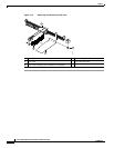
Step 2 Install a SAS extender or SAS expander card:
Note Upgrades from a SAS extender to a SAS expander are not supported in the field. Replace an extender or
expander only with the same type of card.
a. Set the new card into the chassis so that the keyed slots in the card fit over the pegs on the chassis
floor.
b. Slide the card toward the server front until its edge connectors engage the backplane and the keyed
slots in the card lock onto the pegs.
c. Replace the single securing screw to the card.
d. Replace the power harness cable to the connector on the corner of the card.
e. Replace controller cables to the connectors on the card.
f. Replace the front cover as described in Removing and Replacing the Server Front Cover, page 3-11.
g. Replace the top cover.
h. Replace the server in the rack, replace power cords and any other cables, and then power on the
server by pressing the Power button.