


3-26
Cisco UCS C210 Server Installation and Service Guide
OL-20887-02
Chapter
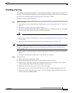
Installing CPUs and Heatsinks
The qualified and supported part numbers for this component are subject to change over time. For the most
up-to-date list of replaceable components, see the following URL and then scroll to Technical Specifications:
http://www.cisco.com/en/US/products/ps10493/products_data_sheets_list.html
This section contains the following topics:
• Additional CPU-Related Parts To Order With RMA Replacement Motherboards, page 3-26
• CPU Replacement Procedure, page 3-26
Additional CPU-Related Parts To Order With RMA Replacement Motherboards
When a return material authorization (RMA) of the motherboard or CPU is done on a Cisco UCS
C-series server, there are additional parts that might not be included with the CPU or motherboard spare
bill of materials (BOM). The TAC engineer might need to add the additional parts to the RMA to help
ensure a successful replacement.
• Scenario 1—You are re-using the existing heatsinks:
–
Heat sink cleaning kit (UCSX-HSCK=)
–
Thermal grease kit for C210 (UCS-CPU-GREASE=)
• Scenario 2—You are replacing the existing heatsinks:
–
Heat sink (R200-BHTS1=)
–
Heat sink cleaning kit (UCSX-HSCK=)
A CPU heatsink cleaning kit is good for up to four CPU and heatsink cleanings. The cleaning kit contains
two bottles of solution, one to clean the CPU and heatsink of old thermal interface material and the other
to prepare the surface of the heatsink.
New heatsink spares have preinstalled thermal interface material covered by a small sheet of plastic. It
is important to clean the old thermal interface material off of the CPU prior to installing the heatsinks.
Therefore, when ordering new heatsinks it is still necessary to order the heatsink cleaning kit at a
minimum.
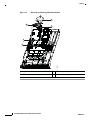
CPU Replacement Procedure
To install or replace a CPU and heatsink, follow these steps:
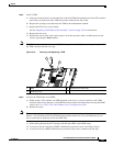
Step 1 Remove an existing CPU and heatsink:
a. Power off the server as described in the “Shutting Down and Powering Off the Server” section on
page 3-8.
b. Disconnect all power cords from the power supplies.
c. Slide the server out the front of the rack far enough so that you can remove the top cover. You might
have to detach cables from the rear panel to provide clearance.
Caution If you cannot safely view and access the component, remove the server from the rack.
d. Remove the top cover as described in the “Removing and Replacing the Server Top Cover” section
on page 3-10.
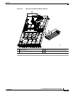
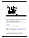
e. Remove the air duct that sits over the CPUs and set it aside. To remove the duct, depress the plastic
latch on each end of the duct to disengage it from the chassis standoff posts.