


3-12
Cisco UCS C210 Server Installation and Service Guide
OL-20887-02
Chapter
Replaceable Component Locations
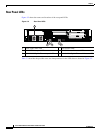
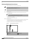
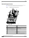
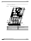
This section shows the locations of the components that are discussed in this chapter. The view in
Figure 3-5 is from the top down, with the top cover and internal air baffle removed.
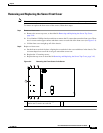
Figure 3-5 Replaceable Component Locations (top view)
1 Hard drives (up to 16, accessible through front
bays)
2 DVD drive
3 Fan tray 4 DIMM slots (up to 12)
5 CPUs and heatsinks (up to two) 6 CMOS battery
7 PCIe card slot for riser card (with chassis
openings for three standard-profile cards)
8 Riser card assembly
9 PCIe card slot for riser card (with chassis
openings for two standard-profile cards)
10 Socket for trusted platform module (TPM)
11 Socket for LSI mezzanine card 12 Power supplies (up to two, accessible through
rear bays)
13 Internal USB port on motherboard
(active in server Generation M2 only)
7
8
9 11
10
12
4
3
5
6
195918
12
13