


3-34
Cisco UCS C210 Server Installation and Service Guide
OL-20887-02
Chapter
Replacing a PCIe Card
This section contains the following topics:
• Replacing a PCIe Card, page 3-34
• Special Considerations for the Cisco UCS P81E Virtual Interface Card (N2XX-ACPCI01),
page 3-37
• Installing Multiple PCIe Cards and Resolving Limited Resources, page 3-38
Note For more information about RAID controller cards and RAID controller cabling, see the RAID
Controller Considerations, page C-1.
Note If you are installing a Cisco UCS P81E Virtual Interface Card (N2XX-ACPCI01), there are prerequisite
considerations. See
Special Considerations for the Cisco UCS P81E Virtual Interface Card
(N2XX-ACPCI01), page 3-37.
The qualified and supported part numbers for this component are subject to change over time. For the most
up-to-date list of replaceable components, see the following URL and then scroll to Technical Specifications:
http://www.cisco.com/en/US/products/ps10493/products_data_sheets_list.html
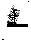
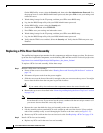
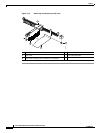
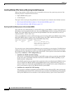
Installing a PCIe card requires that you first remove the riser card assembly from the chassis. The PCIe
slot numbering on the riser card assembly is shown in
Figure 3-18 (as viewed from the rear of the server):
Figure 3-18 PCIe Slot Numbering and Physical Orientation, Facing Server Rear
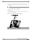
Replacing a PCIe Card
To install or replace a PCIe card, follow these steps:
Step 1 Remove a PCIe card:
a. Power off the server as described in the “Shutting Down and Powering Off the Server” section on
page 3-8.
b. Disconnect all power cords from the power supplies.
c. Slide the server out the front of the rack far enough so that you can remove the top cover. You might
have to detach cables from the rear panel to provide clearance.
Caution If you cannot safely view and access the component, remove the server from the rack.
d. Remove the top cover as described in the “Removing and Replacing the Server Top Cover” section
on page 3-10.
PCIe Slot 4 PCIe Slot 1
PCIe Slot 5 PCIe Slot 2
PCIe Slot 3