


2-7
Cisco UCS C210 Server Installation and Service Guide
OL-20887-02
Chapter
d. Attach the second slide-rail assembly to the opposite side of the rack. Ensure that the two slide-rail
assemblies are level and at the same height with each other.
e. Pull the inner slide rails on each assembly out toward the rack front until they hit the internal stops
and lock in place.
Tip You can optionally use the #2 Phillips screws that come with the slide rails to increase stability after
installation. These screws can be installed on the front attachment bracket on each assembly, but are not
required.
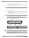
Step 2 Attach mounting brackets to the server:
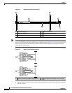
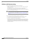
a. Set a mounting bracket (item 3) on the side of the server, aligning its keyed holes over the pegs on
the server (item 2). The plastic installation release clip (item 5) on the bracket should be toward the
server front. See
Figure 2-4.
b. Push the mounting bracket toward the server rear until the locking clip clicks over the server peg.
c. Attach the remaining mounting bracket to the opposite side of the server.
Tip You can optionally use the #1 Phillips screws that come with the slide rails to increase stability after
installation. You can install two of these screws on each side of the server to more permanently attach
the mounting brackets to each side of the server, but they are not required.
Figure 2-4 Attaching Mounting Brackets to the Server
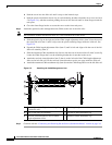
Step 3 Insert the server into the slide rails:
Caution This server weighs approximately 50 pounds (23 kilograms) when fully loaded with components. We
recommend that you use a minimum of two people when lifting the server. Attempting this procedure
alone could result in personal injury or equipment damage.
a. Align the mounting brackets that are attached to the server sides with the front of the empty slide
rails.
1 Rear of server 2 Mounting peg (four)
3 Mounting bracket 4 Removal release clip
5 Installation release clip
195955
1
3 4 5
2