


3-11
Cisco UCS C210 Server Installation and Service Guide
OL-20887-02
Chapter
Removing and Replacing the Server Front Cover
Note It is not necessary to remove the front cover unless instructed to do so in a replacement procedure.
To remove or replace the front cover of the server, follow these steps:
Step 1 Remove a front cover:
a. Remove the server top cover, as described in Removing and Replacing the Server Top Cover,
page 3-10.
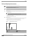
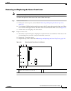
b. Use a Number 1 Phillips-head screwdriver to remove the 12 screws that secure the front cover. There
are six screws on the upper surface and three screws on each side of the front cover (see
Figure 3-4).
c. Lift the front cover straight up off of the chassis.
Step 2 Replace a front cover:
a. Set the front cover back in place, aligning the screw holes in the cover with those in the chassis. The
crescent-shaped cut-out on the cover goes toward the server rear.
b. Replace the 12 securing screws.
c. Replace the top cover as described in Removing and Replacing the Server Top Cover, page 3-10.
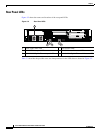
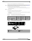
Figure 3-4 Removing the Front Cover of the Server
1 Front cover, with 6 screws on the upper
surface and 3 screws on each side
1
195917