


3-10
Cisco UCS C210 Server Installation and Service Guide
OL-20887-02
Chapter
Removing and Replacing the Server Top Cover
To remove or replace the top cover of the server, follow these steps:
Warning
This unit might have more than one power cord. To reduce the risk of electric shock, disconnect the
two power supply cords before servicing the unit.
Statement 14
Tip You do not have to remove the cover to replace hard drives or power supplies.
Step 1 Remove the top cover:
a. Use a Number 2 Phillips-head screwdriver to remove the screw that secures the top cover
(Generation M1 only).
Note The UCS C210 Generation M2 server does not have a cover screw.
b. Press down on the release button and use the nonslip pad to push the cover toward the rear about one
inch, until you feel it stop sliding.
c. Lift the cover from the server and set it aside.
Step 2 Replace the top cover:
a. Set the cover in place about one inch back from the fully closed position. Use the three alignment
pegs on each inside edge of the cover to align with the alignment notches on the chassis.
b. Push the cover toward the server front until the release button clicks.
c. Replace the screw that secures the cover in place (Generation M1 only).
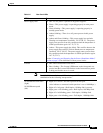
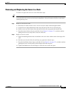
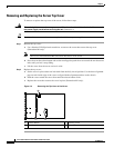
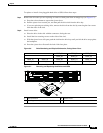
Figure 3-3 Removing the Top Cover of the Server
1 Release button 2 Securing screw
3 Nonslip pad
32
1
195913