


3-31
Cisco UCS C210 Server Installation and Service Guide
OL-20887-02
Chapter
Step 2 Install a TPM:
a. Align the connector that is on the underside of the new TPM with motherboard socket JP2, and then
press firmly on both ends of the TPM to press the connector into the socket.
b. Replace the securing screw that holds the TPM to the motherboard standoff.
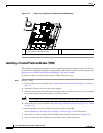
c. Replace the PCIe riser card assembly.
See the “Replacing a PCIe Riser Card Assembly” section on page 3-32 for instructions.
d. Replace the top cover.
e. Replace the server in the rack, replace power cords and any other cables, and then power on the
server by pressing the Power button.
Note The TPM must be enabled in the server BIOS before you can use it. If you have not previously enabled
the TPM, continue with the next step.
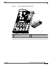
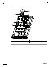
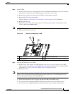
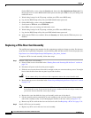
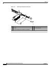
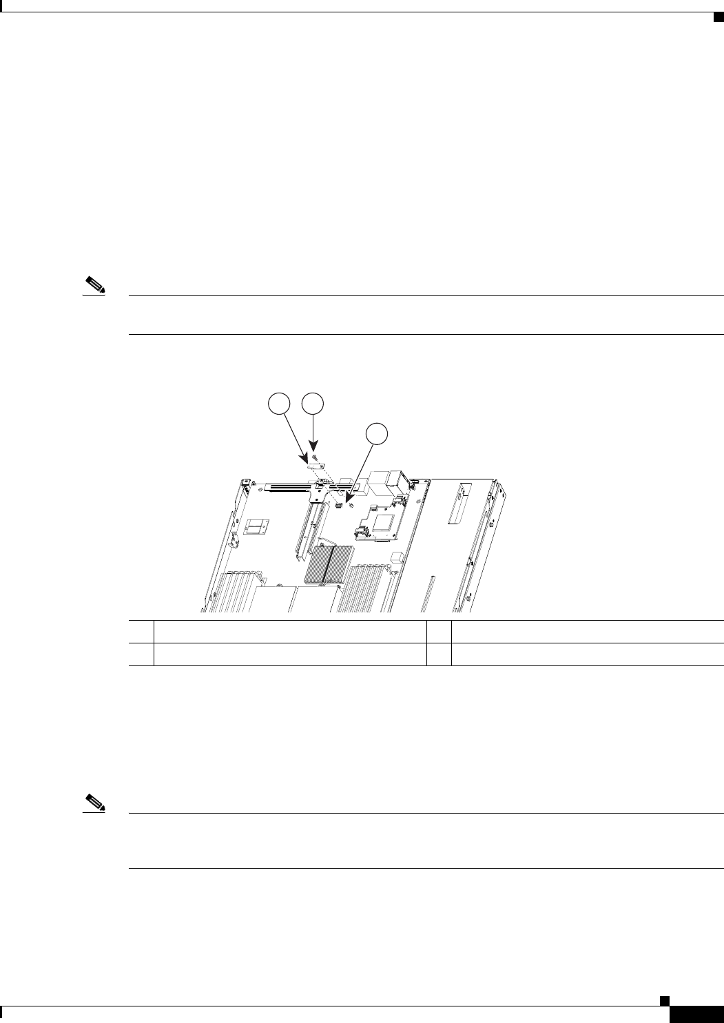
Figure 3-16 Removing and Replacing a TPM
Step 3 Activate the TPM in the server BIOS:
a. Either attach a VGA monitor and USB keyboard to the server, or log in remotely to the CIMC
interface of the server and open a virtual KVM console window. For instructions on using the CIMC,
refer to the Cisco UCS C-Series Rack-Mount Server Configuration Guide.
b. Reboot the server.
Note You can reboot the server by pressing the Power button on the server; by selecting
Macros > Ctrl-Alt-Del on the Cisco KVM Console window menu bar; or by selecting Power Cycle
Server on the Server Summary tab of the CIMC GUI.
c. Watch during bootup for the F2 prompt, and then press F2 to enter BIOS setup.
d. If you have already configured a BIOS Administrator password, enter it and skip to Step h.
e. If you have not set a BIOS Administrator password for the server, continue with this step.
1 TPM 2 Motherboard socket JP2
3 Securing screw
3
1
2