


3-2
Cisco UCS C210 Server Installation and Service Guide
OL-20887-02
Chapter
Status LEDs
This section describes the locations and interpretations of LEDs on the server that can provide status and
troubleshooting information. This section includes the following topics:
• Front Panel LEDs, page 3-2
• Rear Panel LEDs, page 3-4
Front Panel LEDs
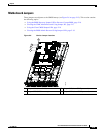
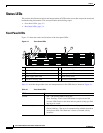
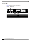
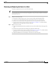
Figure 3-1 shows the names and locations of the front panel LEDs.
Figure 3-1 Front Panel LEDs
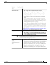
Table 3-1 describes the possible states and interpretations for the LEDs that are shown in Figure 3-1.
1 Locator LED/Locator button 2 Network activity LED
3 System fault LED 4 Power status LED/Power button
5 CPU fault LED 6 Memory fault LED
7 Power supply fault LED 8 DVD activity LED
9 Hard drive activity LED 10 Hard drive fault LED
195915
1
4
9
5
2
3
6
7
10
8
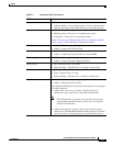
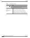
Ta b l e 3-1 Front Panel LEDs
LED Name State
Locator • Off—The Locator LED is not in use.
• Blue, flashing—The Locator LED button was pressed and the
Locator LED flashes on the front and rear panels to help you find
the server in a rack.
Network activity • Off—The server is powered off or in standby power mode.
• Green, blinking—The server is communicating with the network in
main power mode. The blink rate is faster as network activity
increases.