


3-22
Cisco UCS C210 Server Installation and Service Guide
OL-20887-02
Chapter
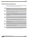
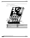
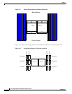
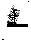
Figure 3-11 Physical Representation of Banks and Channels
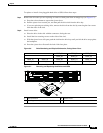
Figure 3-12 shows a logical representation of the channels and banks associated with each CPU.
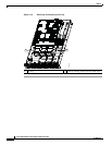
Figure 3-12 Logical Representation of Channels and Banks
CPU2 CPU1
F1 F2 D1 D2E1 E2 A2 A1 C2 C1B2 B1
Front of Server
Rear of Server
CPU1CPU2
Channel D
Channel E
Channel F
Bank 2
Bank 1
D2
D1
E2
E1
F2
F1
A1
A2
B1
B2
C1
C2
Bank 2
Bank 1
Channel A
Channel B
Channel C