


3-35
Cisco UCS C210 Server Installation and Service Guide
OL-20887-02
Chapter
Note Older servers have a screw that secures the PCIe riser to the rear of the chassis, but newer servers
do not have this screw. If your server has the screw, continue with the next step to remove it. If
your server does not have this screw, skip to Step f.
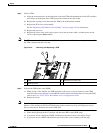
e. Remove the screw that holds the riser card assembly to the rear of the chassis.
f. Disconnect any cables from connectors on the PCIe card.
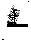
g. Lift the assembly and any attached PCIe cards straight up and out of the chassis. Lift up on both
ends of the assembly evenly to avoid damaging the sockets or the riser cards. See
Figure 3-17 on
page 3-33.
h. Remove the screw that secures the PCIe card rear plate to the assembly rear opening.
i. Pull the PCIe card connector out of the riser card socket and set the card aside.
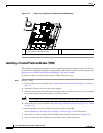
Step 2 Install a PCIe card:
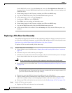
a. If you are installing a PCIe card to an empty slot on the riser card assembly, remove any blank panel
from the assembly rear opening by removing the screw that secures the blank panel.
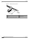
b. Align the PCIe card connector with the riser card socket and push on both ends of the card evenly
to fully engage the card connector with the riser card socket (see
Figure 3-19).
c. Install the screw that secures the rear plate of the card to the assembly rear opening.
d. Replace any cables that were connected on the old card to connectors on the new card.
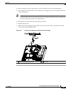
e. Set the assembly in place, aligning the riser cards with the PCIe slots on the motherboard.
f. Press down evenly on both ends of the assembly to fully engage the riser cards with the PCIe slots
on the motherboard.
Note Older servers have a screw that secures the PCIe riser to the rear of the chassis, but newer servers
do not have this screw. If your server has the screw, continue with the next step to replace it. If
your server does not have this screw, skip to Step h.
g. Replace the screw that secures the assembly to the chassis.
h. Replace the top cover.
i. Replace the server in the rack, replace power cords and any other cables, and then power on the
server by pressing the Power button.