


3-42
Cisco UCS C210 Server Installation and Service Guide
OL-20887-02
Chapter
Replacing an LSI MegaRAID Battery Backup Unit
When you install an LSI MegaRAID card and the optional BBU in this server, do not install the BBU on
top of the card as described in the LSI instructions. To avoid overheating the card, you must install the
BBU on a special bracket that is located on the top of the power supply bay.
Note LSI recommends that you replace the LSI BBU once per year or after 1,000 recharge cycles, whichever
comes first. Verify whether BBU replacement is required by looking in the CIMC. Log in to CIMC for
the server, then click Server—Inventory—Storage—Battery Backup Unit. If the Battery Replacement
Required field says, “True,” then you must purchase a replacement BBU and replace it.
Warning
There is danger of explosion if the battery is replaced incorrectly. Replace the battery only with the
same or equivalent type recommended by the manufacturer. Dispose of used batteries according to
the manufacturer’s instructions.
[Statement 1015]
The qualified and supported part numbers for this component are subject to change over time. For the most
up-to-date list of replaceable components, see the following URL and then scroll to Technical Specifications:
http://www.cisco.com/en/US/products/ps10493/products_data_sheets_list.html
To install or replace an LSI BBU, follow these steps:
Step 1 Remove a BBU:
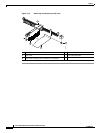
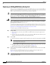
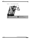
a. Remove the three screws that secure the BBU to the BBU bracket on the power supply bay (see
Figure 3-22).
b. Disconnect the cable from the BBU. If you are only replacing a BBU and not the LSI card, you do
not have to disconnect the other end of the cable from the card.
Step 2 Install a BBU:
a. Install the cable that is attached to the LSI controller card to socket J2 on the underside of the BBU.
Note Be careful to align the arrow-mark on the cable connector with the arrow-mark on the socket to
avoid damaging the connector pins.
b. Place the new BBU over the BBU bracket on the power supply bay and align the three screw-holes
in the BBU with the three screw-holes on the bracket (see
Figure 3-22).
c. Replace the three securing screws that hold the BBU to the BBU bracket.
Step 3 If this is a first-time installation of the BBU rather than a replacement, install the cable from the BBU
to the LSI card:
Route the cable from the BBU through the cable access opening on the power supply bay (see
Figure 3-22) and then connect the cable to the socket on the adapter.
Note Be careful to align the arrow-mark on the cable connector with the arrow-mark on the socket to avoid
damaging the connector pins.