


91
7 Technical Reference
This section includes:
• Connector pinouts
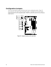
• Information on jumpers
Connector Pinouts
This section describes certain I/O interface connectors of the xSeries 343 server.
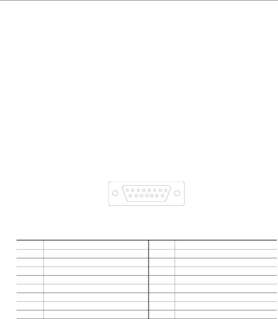
Alarms
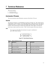
The alarms port interface is a standard DB15-pin connector (see Figure 34). This connector allows
remote display of alarm conditions. Each alarm (Major, Minor, Critical and Power) is the output of
a STDT relay contact. A common contact with normally open and normally closed connections is
included. Power alarm has just a common and normally open contact outputs. The major and
minor alarms contain external reset circuits. Table 12 gives the pinout of the alarms connector.
Note
Do not apply more than 60 Volts (maximum) to any pin or combination of
pins on the Alarms connector.
18
915
Figure 34. 15-pin Alarms Connector
Table 12. Alarms Connector Pinout
Pin Description Pin Description
1 Minor reset positive 9 Minor alarm normally closed
2 Minor reset negative 10 Minor alarm common
3 Major reset positive 11 Major alarm normally open
4 Major reset negative 12 Major alarm normally closed
5 Critical alarm normally open 13 Major alarm common
6 Critical alarm normally closed 14 Power alarm normally open
7 Critical alarm common 15 Power alarm common
8 Minor alarm normally open