


70 xSeries 343 Hardware Maintenance Manual
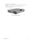
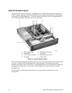
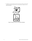
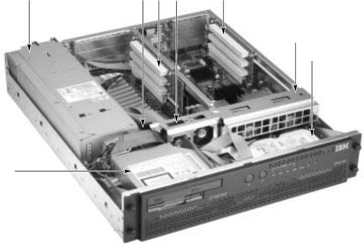
Internal Chassis Layout
The server board contains connectors for installing up to two Pentium III processors utilizing the
FCPGA sockets. The server board has 6 DIMM slots and supports up to 6 GB error checking and
correcting (ECC) SDRAM memory. The server board also contains 6 PCI slots (implemented via
riser cards), input/output (I/O) ports and various controllers.
OM14190
H
C
B
D
A E
F
G
A Power Supply Cage E 3.3 PCI Add-in Card Riser
B Server Board F Fan Bracket
C 5 V PCI Add-in Card Riser G SCSI Hard Disk Drive Tray
D Fan Module H Peripheral Bay
Figure 15. Internal Chassis Layout
The server board is mounted horizontally toward the rear of the chassis behind the system fan array.
Up to two, 1.0-inch SCSI Ultra160 hard drives can be mounted in the hard drive tray that is
mounted at the bottom front of the chassis. Above the hard drive tray and to the left are located the
peripheral drives that consist of a slim-line (1/2-inch) floppy drive, and a slim-line (1/2-inch)
CD-ROM drive.
The front panel is located above the hard drive tray and provides user interface for system
management.