


26 xSeries 343 Hardware Maintenance Manual
Cooling Subsystem
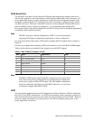
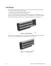
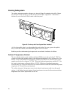
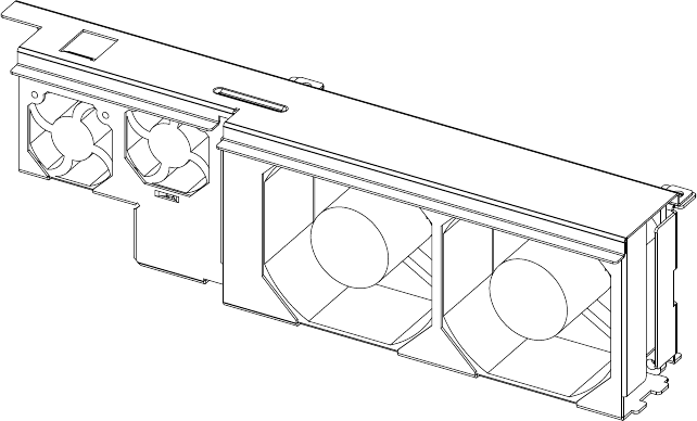
The cooling subsystem contains a fan array (as shown in Figure 9) consisting of two 80 x 38 mm
fans and two 40 x 28 mm fans to cool the server board and other components. A fan failure is
indicated by one of the fault LEDs located on the front panel.
OM12820
Figure 9. Fan Array with Four System Fans Installed
Air flows through the bezel, over the peripheral bay and the hard drive tray, passes through the
fans, over the server board, and exhausts through the rear of the chassis.
Each fan provides a tachometer signal output to the server board to indicate a fan failure.
Ambient Temperature Control
The server board contains a pulse-width-modulation (PWM) circuit, that cycles the 12 VDC fan
voltage to provide quiet operation when system baseboard temperature is low, and there are no fan
failures. Under normal baseboard temperature conditions (less than 45 °C), the fan power circuit
supplies an effective fan voltage of 7.0 VDC. When the baseboard temperature exceeds 45 °C, the
fan control circuit ceases cycling and delivers 12 VDC. Following a baseboard temperature
excursion above 45 °C the fan voltage does not reenter PWM mode until the baseboard temperature
drops below 45 °C and all fans are operational.
The cooling subsystem’ design meets acoustic and thermal requirements at the lower fan speed
settings. At the higher fan speed settings, thermal requirements are met for the maximum ambient
temperatures but acoustic requirements are not met.