


14 xSeries 343 Hardware Maintenance Manual
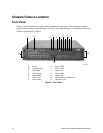
Internal Chassis Features
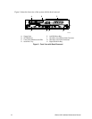
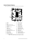
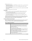
Figure 5 shows the location of the server board’s connectors and other components.
OM12815
H
JF I
L
M
PX N
OQ
R
S
TV
UW
CC
BB
Y
A C D E
FF
EE
DD
B
Z
AA
K
GG
G
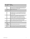
A
Speaker R Sys fan 2 connector
B
ID LED S CPU 1 fan connector
C
Battery T Sys fan 1 connector
D
Diagnostic LEDs (POST code) U Aux fan connector
E
66 MHz/64-bit PCI riser slot (full height) V Floppy drive connector
F
DIMM slots W Fan module connector
G
DCD/DSR jumper block X Main power connector
H
I/O ports Y Auxiliary signal connector
I
ICMB connector Z Floppy/FP/IDE connector
J
COM1 serial header AA Alternate front panel connector
K
Chassis intrusion connector BB ATA/IDE connector
L
66 MHz/64-bit PCI riser slot (low profile) CC IPMB connector
M
USB 3 & 4 header DD SSI front panel connector
N
Sys fan 3 connector EE Configuration jumper block
O
CPU 2 fan connector FF SCSI connector (SCSI version only)
P
Secondary processor socket GG Hard Disk Drive LED header
Q
Primary processor socket
Figure 5. Server Board Connector and Component Locations