


24 xSeries 343 Hardware Maintenance Manual
Introduction
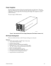
The xSeries343 server system uses a -48 to -60 VDC input switching power subsystem, which
provides up to 350 Watts with -48 to -60 VDC input and with current and remote sense regulation.
The power subsystem consists of one or two 350-Watt power supply modules. A system with two
modules forms a redundant, hot-swappable (1+1) power subsystem.
Interface Requirements
DC Input
The DC power source may produce hazardous voltage levels exceeding -60 VDC and high energy
levels above 240VA that may cause electric shock or burns. All DC input connections should be
made only by a qualified service person only to prevent injury. All wiring terminals connected to
the DC input terminal block must be fully insulated with no exposed bare metal.
DC Output Connectors
The power subsystem DC power and control signals are interfaced to the server system via wire
harnesses when the power supply modules are inserted into the power subsystem enclosure. The
safety ground pin of the power supply module is the first pin to connect and the last to disconnect
when the module is being inserted or removed from the power subsystem housing. In addition to
the 5 V Standby, -12 V, +3.3 V, +5 V and +12 V DC outputs, the following signals and output pins
are included:
• +3.3 VDC remote sense
• +5 VDC remote sense
• +12 VDC remote sense
• Remote sense return
• Power Subsystem On (DC PWR enable)
• Power Good
• I
2
C
*
*
PS Failure, PS Presence, PS Predictive Fail, +12 V Mon, +5 V Mon, and the 5 V Standby rails
failure are being monitored via an I
2
C interface chip.
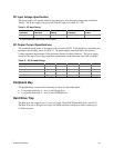
Power Supply Module LED Indicators
There is a single bi-color LED to indicate power supply status visible on the back of the system.
Table 8 shows the conditions confirmed by the LED indicators.
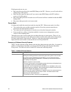
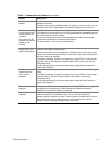
Table 8. LED Indicators
Power Supply Condition Power Supply LED
No DC power to all PSU OFF
No DC power to this PSU only AMBER
DC present / Only Standby Outputs On BLINK GREEN
Power supply DC outputs ON and OK GREEN
Power Supply in Alert Condition BLINK AMBER
Power supply failure (OTP, OCP, OVP, UV) AMBER