


12
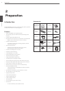
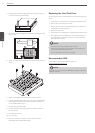
Installation
3
Installation
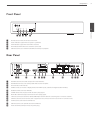
Connecting Display device
This unit can be output simultaneously from the HDMI and VGA
jack. The video signal connects between the system and the
monitor.
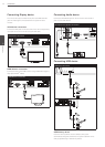
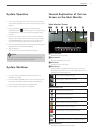
VGA Monitor connection
Connect the VGA jacks on the rear of the unit to the corresponding
input jacks on the TV or monitor using the VGA cable.
VGA Monitor connection
IN
OUT
VGA
HDMI
2
4
1
3
E-SATA
USB
5 V 0.5 A
LAN
DC 48 V
CAM
AUDIO
- + 1 2 3 4 G 1 2 G
IN
OUT
ALARM
RS
485
IN
OUT
VGA
HDMI
2
4
1
3
E-SATA
USB
5 V 0.5 A
LAN
DC 48 V
CAM
AUDIO
- + 1 2 3 4 G 1 2 G
IN
OUT
ALARM
RS
485
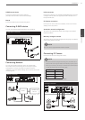
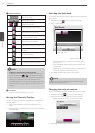
HDMI Monitor connection
Connect the unit to the HDMI monitor using a HDMI cable (Type A,
High Speed HDMI
TM
Cable).
HDMI Monitor connection
IN
OUT
VGA
HDMI
2
4
1
3
E-SATA
USB
5 V 0.5 A
LAN
DC 48 V
CAM
AUDIO
- + 1 2 3 4 G 1 2 G
IN
OUT
ALARM
RS
485
IN
OUT
VGA
HDMI
2
4
1
3
E-SATA
USB
5 V 0.5 A
LAN
DC 48 V
CAM
AUDIO
- + 1 2 3 4 G 1 2 G
IN
OUT
ALARM
RS
485
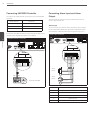
Connecting Audio device
Connect the AUDIO OUT jacks on the unit to the mono audio in
jacks on your audio device.
Microphone and Speaker connection
IN
OUT
VGA
HDMI
2
4
1
3
E-SATA
USB
5 V 0.5 A
LAN
DC 48 V
CAM
AUDIO
- + 1 2 3 4 G 1 2 G
IN
OUT
ALARM
RS
485
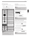
Connecting USB device
USB device connection
IN
OUT
VGA
HDMI
2
4
1
3
E-SATA
USB
5 V 0.5 A
LAN
DC 48 V
CAM
AUDIO
- + 1 2 3 4 G 1 2 G
IN
OUT
ALARM
RS
485
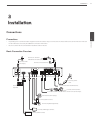
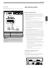
POWER
HDD LAN
H.264 Network Video Recorder
IN
OUT
VGA
HDMI
2
4
1
3
E-SATA
USB
5 V 0.5 A
LAN
DC 48 V
CAM
AUDIO
- + 1 2 3 4 G 1 2 G
IN
OUT
ALARM
RS
485
POWER
HDD LAN
H.264 Network Video Recorder
USB Memory device
Insert the memory device into the USB port. The system
automatically recognizes the device. The system software can be
easily upgraded using a USB memory device.