


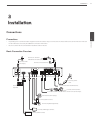

Installation
15
3
Installation
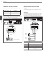
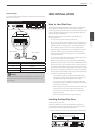
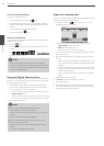
Alarm Output
Connect the alarm device to the alarm output. Alarm signal outputs
when an event occur.
Alarm output connection
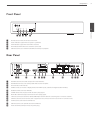
IN
OUT
VGA
HDMI
2
4
1
3
E-SATA
USB
5 V 0.5 A
LAN
DC 48 V
CAM
AUDIO
- + 1 2 3 4 G 1 2 G
IN
OUT
ALARM
RS
485
HDMI
2
4
1
3
E-SATA
USB
5 V 0.5 A
LAN
DC 48 V
CAM
- + 1 2 3 4 G 1 2 G
IN
OUT
ALARM
RS
485
IN
OUT
VGA
HDMI
2
4
1
3
E-SATA
USB
5 V 0.5 A
LAN
DC 48 V
CAM
AUDIO
- + 1 2 3 4 G 1 2 G
IN
OUT
ALARM
RS
485
HDMI
2
4
1
3
E-SATA
USB
5 V 0.5 A
LAN
DC 48 V
CAM
- + 1 2 3 4 G 1 2 G
IN
OUT
ALARM
RS
485
IN
OUT
VGA
HDMI
2
4
1
3
E-SATA
USB
5 V 0.5 A
LAN
DC 48 V
CAM
AUDIO
- + 1 2 3 4 G 1 2 G
IN
OUT
ALARM
RS
485
IN
OUT
VGA
HDMI
2
1
LAN
AUDIO
- + 1 2 3 4 G 1 2 G
IN
OUT
ALARM
RS
485
TX+TX-
Alarm device
Alarm device
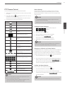
Terminal No. Description
G Ground
1 Alarm Output 1
2 Alarm Output 2
NOTE
The internal switching relays are rated for 0.3 A at 125 V AC or 1 A
at 30 V DC. If the electric current is higher than that the unit can
be damaged.
HDD INSTALLATION
Note for Hard Disk Drive
The internal hard disk drive (HDD) is a fragile piece of equipment.
Please follow the guidelines below when using the system to
protect against possible HDD failure. We recommend that you back
up your important recordings onto an external backup device in
order to prevent accidental loss.
Make sure that the power is turned OFF when attaching or
removing the HDD.
• Do not move the system while the power is on.
• Do not use the system in excessively hot or humid places, or in
places that may be subject to sudden changes in temperature.
Sudden changes in temperature can cause condensation to
form inside the system. This can be a cause of HDD failure.
• While the system is switched on, do not unplug from the wall
socket or switch the electricity off from the breaker switch.
• If there’s a power failure while the system is on, some data on
the HDD may be lost.
• Do not drop the HDD. Also do not put the metallic object such
as coins or screwdrivers into the HDD tray.
• When a power failure occurs during recording, avoid adding,
replacing or transporting the HDD as the recorded data may be
erased. In this case, turn the power back on to boot up the unit
normally with the HDD that was being used at the time of the
power failure attached. Then add, replace, or transport the HDD.
• The HDD is very delicate. Handle the HDD with care and follow
the precautions below because even a tiny shock may damage
the internal components of the HDD.
- Do not place the HDD on the desk or table directly. Put a
thick cushion under the HDD because even a small shock
may damage the internal components of the HDD.
- Do not use an electric screwdriver. Vibrations and shocks
caused by an electric screwdriver may damage the internal
components of the HDD.
- When replacing the HDD, do not knock the HDD with other
components such as another HDD and the HDD tray.
- Do not knock the HDD with tools such as a driver when
replacing the HDD.
- Protect the hard disk drives from static electricity.
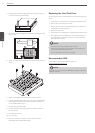
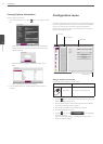
Installing the Hard Disk Drive
You can install up to 1 HDD.
Improper installation or setup may disturb HDD recognition or
normal product operation. So you should consult with an expert
from the store where the product was purchased.
1. Remove the fixing screws on the left/right side and rear panel.
IN
OUT
VGA
HDMI
2
4
1
3
E-SATA
USB
5 V 0.5 A
LAN
DC 48 V
CAM
AUDIO
- + 1 2 3 4 G 1 2 G
IN
OUT
ALARM
RS
485