


11
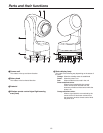
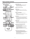
6 Mounting bracket (installed)
7 Tally lamp
This comes on or goes off in response to the control from
the controller but only when “On” has been selected as
the tally lamp use setting.
8 G/L IN connector
This is the genlock signal input connector.
This unit supports the BBS or VBS signal as the genlock
signal.
Connect it to the G/L OUT connector on the cable
compensator (AW-RC400) or other unit.
9 VIDEO OUT connector
This is the output connector for the camera’s composite
video signals. Connect it to a monitor or other such
device. Use a BNC coaxial cable as the connecting cable.
HD/SD ANALOG OUT connector
This is the output connector for the camera’s HD/SD
component video signals.
Use a D-SUB 15-pin connecting cable (VGA cable) or
D-
SUB 15-pin and BNC coaxial connector conversion
cable as the connecting cable.
Use a high-quality cable.
Pin No. Signal name
1 Pr (In
Y/C mode: C)
2 Y (In
Y/C mode: VBS)
3 Pb (In
Y/C mode: Y)
4 to 15 GND
CONTROLLER connector
This is the input connector for the control signals of the
camera unit or pan-tilt head unit.
Connect it to the [TO PAN/TILT HEAD] connector on the
controller.
SERVICE switches
These switches are used for maintenance purposes.
Keep them all at the “OFF” position.
IR ID SET switches
These are used to select the ID of the accessory wireless
remote control.
Switches [1] to [4] correspond to the [CAM1] to [CAM4]
buttons on the wireless remote control.
Wireless remote control signal light-sensing
area (rear)
RESERVE button
This reserve button is used for maintenance purposes.
It is not normally used by the user.
AC IN socket
Connect the accessory power cable to this socket.
Option slot
Parts and their functions