


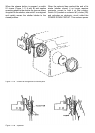
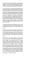
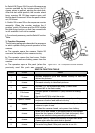
mirror, the 6-edges viewing mirror is used in the
optical path twice. First, the light rays entering
the camera from the taking lens are reected
onto the Fresnel screen by the viewing mirror.
Secondly, the operator views the image on the
screen with light reecting off the viewing mirror
(Figure 2-1). (The viewing mirror is located on
the underside of the mirror cover assembly.)
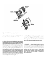
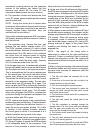
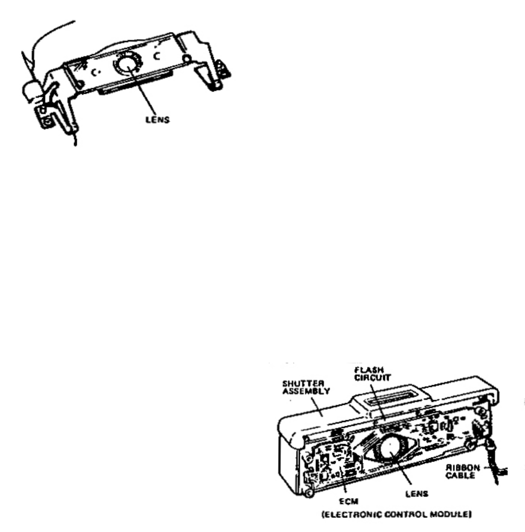
Figure 2-4 Wafer lens assembly
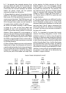
Figure 2-5 ECM - Electronic Control Module
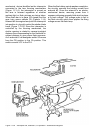
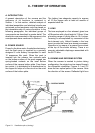
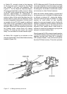
The viewnder optics consist of an eye lens, a
concave mirror and a wafer lens (Figure 2-4). As
in all simple optical system, a certain amount of
distortion is inherent in this design. A small wafer
lens is introduced into the viewnder optical path
to limit to angle of acceptance and, thus, reduce
distortion. The size of the lens opening is large
enough to provide acceptable viewing brilliance
and, at the same time, small enough to be easily
closed when the camera is in the exposure mode.
(On earlier models a rectangular mask called a
stigmatic pupil takes the place of the wafer lens.
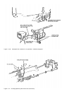
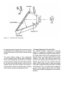
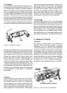
The are bafe (Figure 2-2) is a spring-loaded
plate which springs up when the Fresnel screen
moves into the picture-taking mode. In this state,
light is prevented from passing through the lens
directly onto the lm without rst being reected
off the taking mirror. This prevents «hotspots»
from appearing on the nished picture. When
the Fresnel carrier is in the lowered position, the
are bafe is held down, out of the optical path.
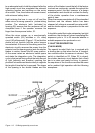
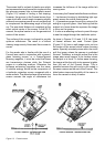
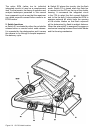
The SX-70 is unique, both in its principles of
operation and its functional design. It can be
considered as aan electronically controlled
mechanical device. An electronic control module
(substrate or ECM) contains all of the electronic
components with the exception of the motor
control (MCC) integrated circuit and the ash re
assembly (FFA). Because the ECM is located
inside the shutteur housing, it becomes identied
as part of the shutter (Figure 2-5). It should
be noted that all of the camera automation is
controlled by the integrated circuits in the ECM.
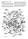
Ignoring the shutter functions momentarily, when
the operators presses the exposure button, the
Fresnel carrier swings away from the lm plane
and comes to rest in front of the viewing mirror.
During the moment of the Fresnel carrier (and
until it returns to its initial viewing position), a
exible light stop closes a path between the
viewnder and the inner camera to prevent light
trough the eye lens from reaching the lm. The
movement of the spring-driven Fresnel carrier is
accomplished by the motor-driven gear train. The
details of the automated action are described
in the discussion of the electro / mechanical
assemblies.
2. Viewnder
4. Flare bafe
1. General
Two rst surface mirrors are used in the SX-70
optical system. When a picture is being taken,
the Fresnel carrier is raised. This places the
4-edges taking mirror into the optical path and
light is reected onto the lm plane. (The taking
mirror is mounted on the Fresnel carrier on the
side opposite the Fresnel screen.) The second
3. Mirrors
E. CAMERA ELCTRONICS