


more times. The READY and FLASH indicator
lamps should sequence as in step 3.
(6) On the ash simulator assembly, press and
release the RESET button.
(7) Press the exposure button actuator. The
number one READY indicator lamp should
remain lighted and the number one FLASH
indicator should not light. (Checks S9.)
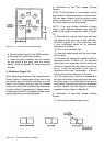
NOTE : The toggle switches on the ash
simulator assembly can be used to simulate
normal or used ash lamps. By settinàg the
individual switches, partially exhausted or
deective ash bars can be simulated.
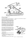
d. Follow-Focus Test
The follow-focus test is used to determine
how well the shutter blade opening follows the
focusing of the lens in ash mode operation.
The APERTURE meter is used in this test.
It is calibrated in stops and when the test is
performed, it will indicate stops deviation from
the ideal design aperture. To perform the follow-
focus test, proceed as follows :
(1) Set the camera focus to innity and the L/D
control to mid-range. Set the power supply to
5.8 volts.
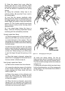
(2) Remove the front cover from the camera
and install the S7 switch actuator.
(3) Install the camera on the horn of the tester.
The camera should go through its dark slide
cycle.
(4) Remove the camera from the tester and set
it on the collimator.
(5) Swing the 8’ and innity lenses into their
vertical positions on the collimator and look
through the camera.
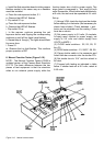
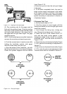
(6) Turn the focus wheel unti the vertical line in
the center target is straight (refer to Figure 3-4).
The camera is now collimated for the 8’ setting.
Tape the focus wheel so it can’t be accidently
moved.
(7) Remove the camera from the collimator and
place it on the tester.
(8) Install the ash simulator plug into the
socket on the camera and close the S2 CLOSE
OPEN SWITCH
(9) Set the light level selector to 800 cdls/ft².
(10) Set the ash mode aperture switch to 8’.
(11) Block any light from the photocell on the
camera using a square of cardboard or other
material.
(12) Depress the exposure button and observe
the APERTURE meter.
(13) Record the 8’ APERTURE reading and
compare it to the STANDARDS Chart.
(14) Remove the tape form the focus wheel
and rotate the wheel to the 10.4’’ setting.
(15) Set the ash mode aperture switch to
10.4’’.
(16) With the photocell still blocked, press the
exposure button and observe the APERTURE
meter.
(17) Record the 10.4’’ APERTURE reading and
compare it to the STANDARD Chart.
(18) If the reading is high at the 8 foot setting,
and the needle goes off scale at the 10.4 ‘‘
setting, the interceptor mechanism is defective.
(See Section IV for repair/adjustment.)
(19) If on scale readings are obtained for 8’
but the 10.4’’ reading is either high or low, the
interceptor can be adjusted. The problem can
be either the interceptor link or the interceptor
cam. (See Section IV for repair/adjustment.)
(20) When repairs/adjustements, «interceptor
on Wrong Side of Stop Pin».
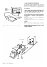
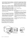
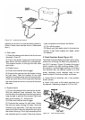
MODEL B CAMERA TESTER
a. Set-up
(1) Be certain that the comparalumen light
source and electronics module are on a at work
surface and plugged into separate 110 VAC
outlets.
(2) Plug the cable assembly from the horn into
the socket located on the front of the electronics
module.
NOTE : There is no warm up time required for
the Model B Tester components.
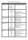
b. Comparalumen Light Specications
The following table shows the luminance levels
of various setting used for camera testing.
c. Ambeint Exposure Measurements
(1) Remove the front cover from the camera.
(2) Close the S7 switch using the S7 actuator.
(3) Set the L/D control to the mid-range position
using the trim reset cam and focus teh camera
at innity.