


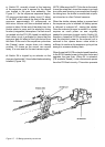
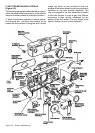
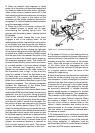
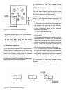
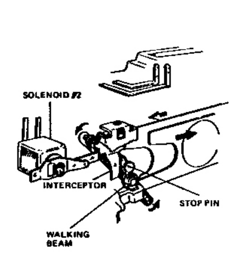
Figure 2-9 A Solenoid S2 operation
2. When an ambeint light exposure is being
made, all of the action just described takes place
but does not affect the shutter action. However,
when a ash array is inserted switch S2 in the
ash socket programs the electronics to energize
solenoid #2. The impact of this action on the
movement of the shutter blades is described in
paragraph F.4. but rst the shutter blade actuation
must be described as follow :
3. When the ECM circuit powers solenoid #1,
the solenoid plunger is pulled into its seat,
overcomming the opening spring force. The
plunger pulls the walking beam, rotating it about
60 degrees.
Each of the shutter blades has a pin which
engages a slot in the walking beam. As the
walking beam rotates, it transmits its rotary motion
to the shutter pins and drives the rear blade to
the right (facing the front of the shutter) and the
front blade to the left thus closing the light path
of the picture taking lens and the light path of the
photocell lens. When the shutter is totally closed
and the gear train has reached the point in the
sequence at which the Fresnel carrier snaps up,
the exposure sequence starts. The blades will
proceed toward the fully open position and retrun
to a closed position in the time interval dictated
by the photocell and integrating circuit. The
blades may not reach the fully open condition if
the illumination level is high, or they may fully
open for a period of time if the light level is low.
If a ash array is mounted, the blades may not
be permittedto open completely because of the
follow focus mechanism described in part in the
foregoing paragraph. The following paragraph
explains the interaction of the follow focus
components and the shutter blades.
4. Installing a ash bar in the camera ash socket
switches the ECM to the ash mode. As previously
explained, at a point in picture taking sequence
(ash mode), solenoid #2 is energized. Fastened
to the plunger is pull down bar. when the plunger
pulls this bar down, it moves the interceptor into
the position where it will intercept a pin (the stop
pin) on the walking beam (Figure 2-9 A). Now
when the shutter blades move towards the open
position, they will be interrupted by the mechanism
just described which means the maximum size
of the blade opening (aperture) is determined by
the focus setting of the camera. As the camera
(and thus the ash lamp) is moved closer to the
subject, the maximum aperture is reduced so
that a correct exposure will result. The reverse
(greater distance/greater aperture) is also true.
5. The shape of the pin on the walking beam si
such that once contacted by the cam interceptor it
remains latched in that position until solenoid #1
actuated during the next phase of the shutter
cycle. When the plunger on solenoid #1 pulls
in, the follow focus pin disengages from the
interceptor and the solenoid #2 plunger returns
to it original position under the force of the
interceptor hinge spring.
6. Since the photocell components are contained
within the shutter housing, they are included in
this discussion. A lens is employed to focus the
reected light from the subject on the photocell.
A second pair of openings in the shutter blades
control the amount of light received by the cell
as previously described. A variable neutrality
density wedge system is employed to provide
lighten / darken adjustements. (Trim assembly).
The operation of this control differs slightly from
those used on other Polaroid cameras. When
the camera is folded, a cam on the shield of
the front cover strikes a release lever on the
lighten / darken assembly and returns the trim
adjusting wheel to its center (normal) position.
The trim wheel is automatically centered when
the camera is closed.
7. To compensate for any variations in individual
photocell characteristics, a neutral density lter
is selected and installed in front of the photocell
lens during assembly. A calibration must be
performed and a lter of correct density installed
any time the ECM requires replacement.