


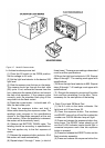
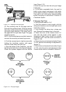
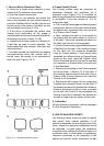

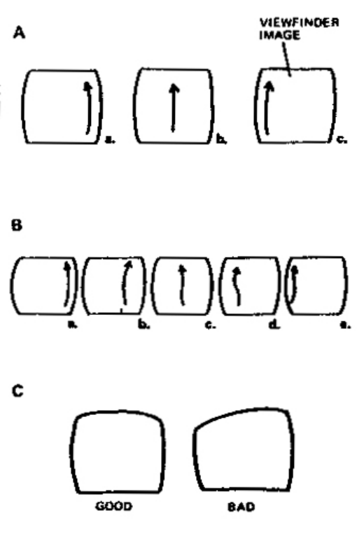
Figure 3-15 Identifying distorted mirrors
3. Concave Mirror Distortion Check
a. Focus on a target which presents a clear
vertical line (for example a door frame).
b. Scan the camera horizontally.
c. If the mirror is not distorted, the vertical line
seen in the eyepiece will vary at the camera is
scanned. At either side of the eld, the line will
be bent while in the center of the eld, the line
will be straight (see Figure 3-15 A).
d. If the mirror is distorted, the vertical lines
change more graphically as the image si
scanned and one or several reversals of direction
of bending may occur (Figure 3-15 B).
e. A telephone directory page at a distance of
2 feet may be used to check distortion. The
white pages have high contrast, ne detail and
uniform printing.
f. The frame around the viewnder may appear
non-sysmmetrical about the vertical axis. A
normal mirror will appear to be sysmmetrical
about the axis (Figure 3-15 C).
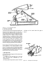
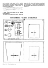
4. Fresnel Quality Check
The Fresnel screen must be examined for
blemishes, shadows, dirt, scratches, etc. A
standards chart (Figure 3-16) is available for
determining whether the Fresnel being examined
is acceptable. Focus the camera to 10.4’’for
viewing the chart.
a. First, view the Fresnel against the background
presented in Section I of the chart. Note whether
the defects (dirt, scratches, digs, etc.) are in the
A or B aera of the Fresnel.
b. Nest, compare any boot or mirror marks on
the Fresnel with the marks shown in Section II
of the chart. If the mark exceeds that shown on
the chart, the Fresnel is not acceptable.
c. View the Frenel screen against the background
of Section III on the chart. The conditions shown
on the chart are the maximum acceptable
limits for Fresnel defects. If the Fresnel being
examined has defects which go beyond those
shown on the chart, reject the Fresnel. (Note
that an illustrated listing on the chart is available
for comparison to Fresnel which have only one
or two blemishes.
d. Examine any shading on the Fresnel against
the limits shown in Section IV of the chart. If
the shading extends beyond the aera (top or
bottom of the Fresnel) shown on the chart, the
Fresnel si not acceptable.
e. Examine teh split image circle by comparong
it against teh examples shown on the chart. If
the shading on the split is greater than shown or
if there is more than one dig, pit, stain, or scratch
on the split, the Fresnel is not acceptable. the
Fresnel must also be rejected if the blemish on
the split is larger than any shown on the chart.
5. Collimation
For the collimation procedure, refer to paragraph
D «Test Equipment Operation».
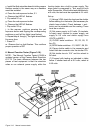
The following charts should be used to identify
and correct faulty camera operation. It will
seldom be necessary to consult every chart. Only
those related to a particular malfunction should
be consulted. In some cases, the customer’s
complaint will be sufciently specic to lead you to
a particular chart. In other cases, the preliminary
inspection procedure at the beginning of this
section will provide usefull information to lead
E. USE OF ANALYSIS CHARTS