


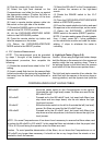
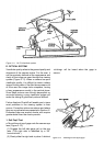
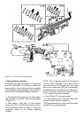

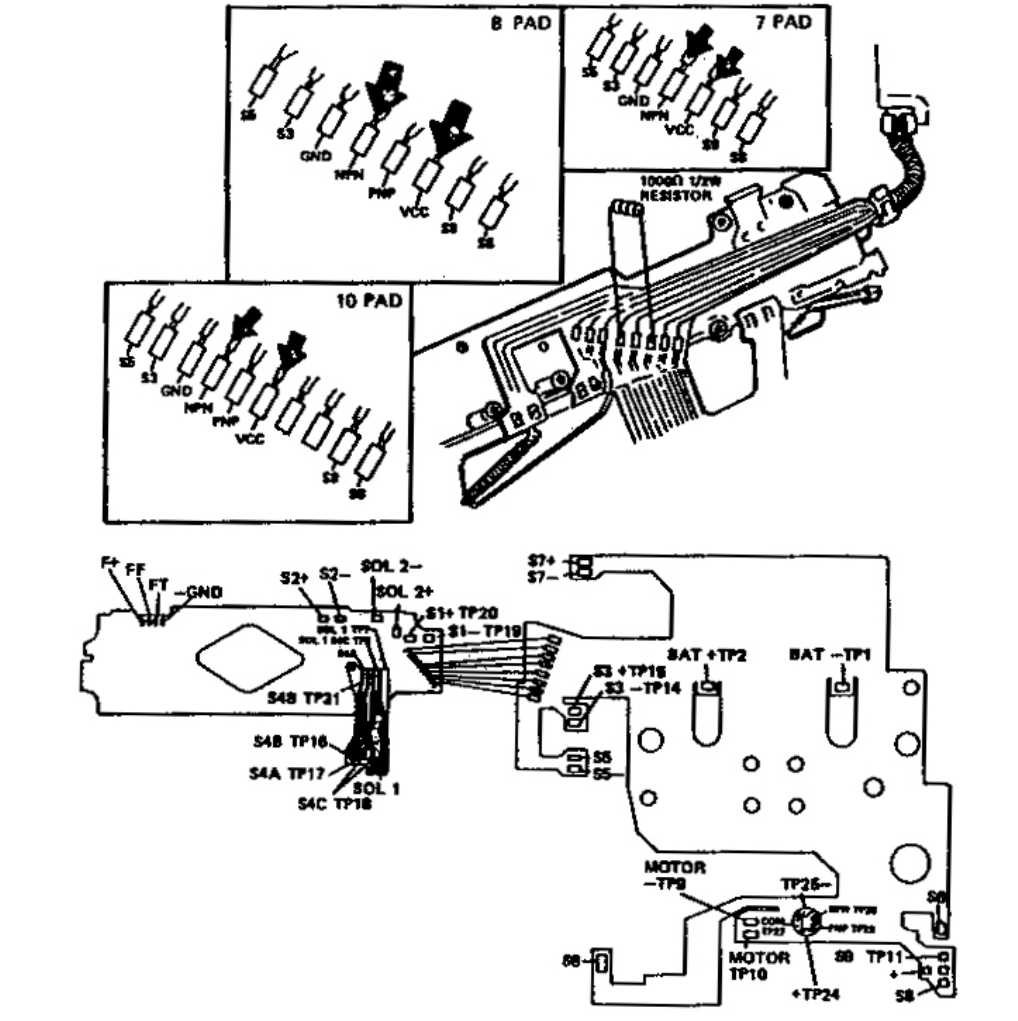
Figure 3-18 Flex circuit terminal locations
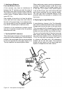
1. Camera/Shutter Isolation
To expedite the repair procedure, it is essential
that the malfunction be isolated to either the
camera back or the shutter as early as possible
in the troubleshooting procedure. The sequence
should not be considered inexible, however.
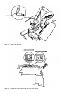
a. Disassemble the camera to the point where
the terminals on the ex circuit are accessible
(Figure 3-17).
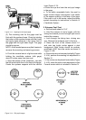
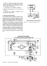
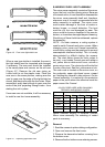
b. Tack solder a 1000 ohm, 1/2 watt resistor
across the VCC and NPN terminals as shown.
(This procedure does not apply to mid-cycle
shutdown. Refer to the Failure Analysis
Charts.)
NOTE : One 10 pad ex circuits, these are the
TP6 and TP30 terminals. One 8 pad circuits,
these are TP4 and TP21 terminals. One 7 pad
ex circuits, where the PNP pad is eliminated,
the NPN terminal is located directly adjacent to
the VCC terminal. Refer to the inserts in Figure
3-17 to locate the proper terminals.
c. Close S6 and S7 and apply power :
(1) If the camera cycles, the motor and MCC
are OK and the shutter is defective.
(2) If the camera fails to cycle, check the motor
and MCC by continuing below.