


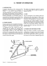
The entire ECM (rather tna its individual
integrated circuits) is used as a remplacement
item. For that reason, the theory of operation and
analysis techniques presented in this manual
have prepared in such a way that the repairman
can relate a specic camera failure mode to an
ECM function.
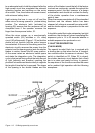
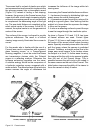
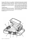
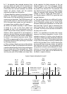
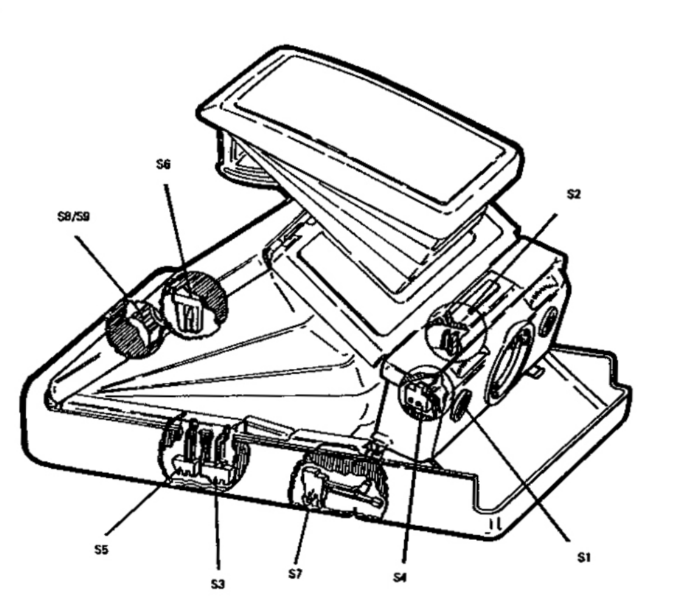
Figure 2-6 SX-70 Switch locations
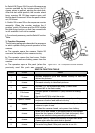
a- Switch S1 is actuated by either the red shutter
release button or remote control cable release.
It is operated by the photographer and it causes
the camera to run through a complet exposure /
lm delevery cycle.
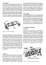
b- Switch S2 places the circuitry into the ash
mode. Switch S2 si closed when the ash bar
is inserted into the FFA on the top of the shutter
housing. It commands the integrated circuit
in the FFA to select the rst unused ashbulb
and, to re the bulb. It also enables the ECM to
energize solenoid #2 which limits the opening
of the shutter blades so that ash exposure
will be determined by ash-to-subject distance.
When the solenoid #2 is energized it engages a
mechanical coupling between the shutter blades
and the focusing mechanism.
2. Switch functions