


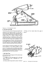
camera in the mirror up picture taking position).
(Both of these tests must be done in a darkened
aera.)
a. Static tests
(1) Erect the camera and remove the front cover
assembly. Close S7.
(2) Turn on the power supply and insert the light
leak xture into the camera lm compartment.
The camera should run through the dark slide
eject cycle.
(3) Darken room.
(4) Press and hold the xture trigger.
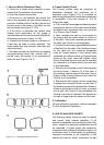
(5) Examine the camera from all angles, looking
for light leaks. Note the location of any light
leaks and continue below with the dynamic test.
(Leak are most likely at the hinge aera between
the inner frame and mirror cover and at the boot
tab aera).
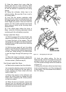
b. Dynamic tests
(1) Cover the photocell lens and trip the shutter.
With the photocell lens coveredn, the mirror
should stay in the raised (picture taking) position
long enough to perform the dynamic light leak
test, approximately 13 - 28 seconds.
(2) Press and hold the xture trigger.
(3) Examine the camera for light leaks. Gently
ex the boot while looking for leaks. Note the
location of any light leaks. (You may see a small
amount of light in the aera where the boot joins
the shutter housing. This is light emanating from
the substrate and is normal.) Allow the camera
cycle completion and remove the xture.
(4) Turn off the power.
(5) Repair any light leaks noted in the previous
testing. If light leaks reparis are made, retest
the camera.
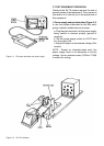
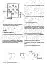
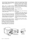
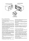
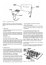
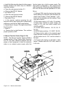
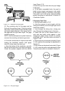
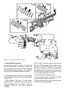
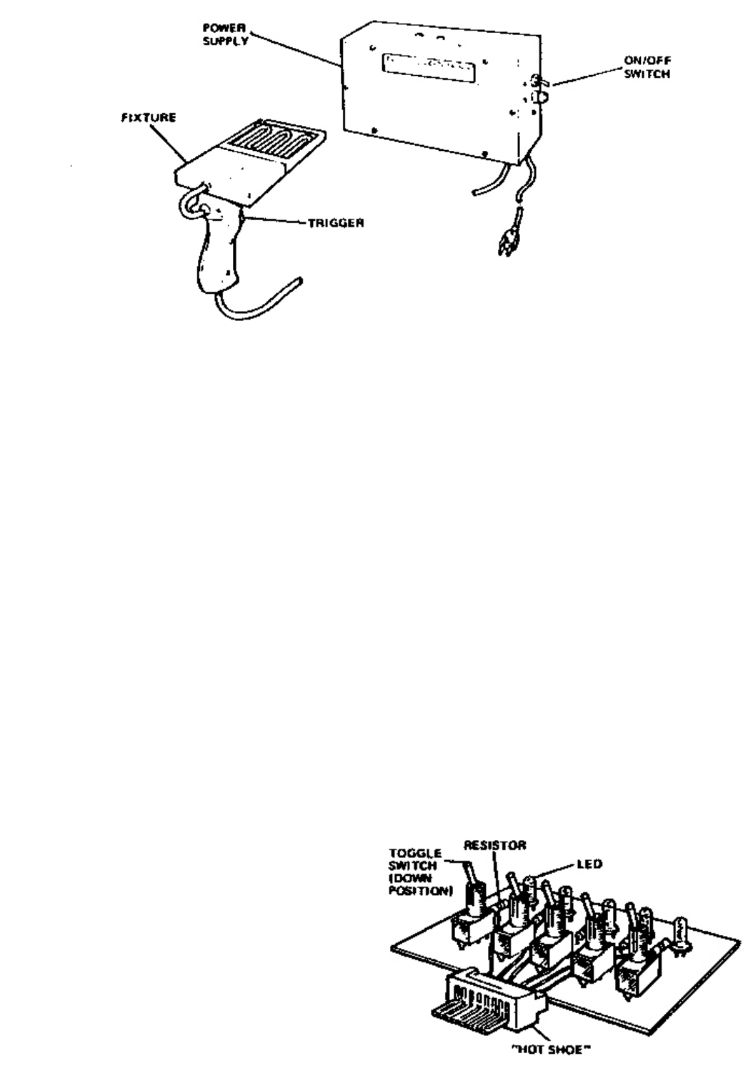
5. Flash Simulator Board (Figure 3-9)
The Flash Simulator Board provides a quick, easy
method for checking the ash ring capability of
the SX-70 camera. Figure 3-9 shows the board
which contains ve light emitting diodes (LED),
ve resistors, and ve toggle switches. Providing
the interface with the camera socket is a «hot
shoe» assembly which reduces wear on the
board contacts. Use the simulator as follows :
a. Insure that all switchers are in the position
shown (down).
b. Insert a lm pack or lm pack simulator into
the camera. Operating voltage is 5.0V to 6.4V.
Figure 3-8 Light leak test system
Figure 3-9 Flash simulator board