


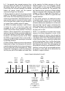
mechanical coupling device set the exposure
counter to the position just before the rst
exposure and closed S8, but since S7 has
removed all battery power no action occurs).
h- At the end of the 40 millisecond delay period,
the ECM removes power from solenoid #1 and the
shutter opens. Simultaneously, the circuit starts
timing the exposure (integration). The integration
components of the ECm are controlled by the
amount of light received by the photocell. At this
time, the ash delay section of the ECM is made
ready but will not function unless a ashbar has
been plugged in, to close switch S2.
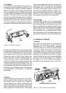
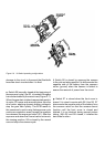
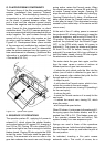
j- When, in the previous step, the solenoid closes
the shutter blades and drive motor is energized,
the gear train resumes its sequence with the
following results :
1. The lm pick feeds the exposed lm to the
spread rolls.
2. At the end of its travel the pick uis held in its
forward position by the pick latch.
3. Film moves through the spread system.
4. The recock gear cam proceeds to retrun the
recock ran which, through the bell crank, moves
the Fresnel carrier down.
5. The recock ram closes switch S3 to prepare for
another exposure.
6. The light stop opens the optical path to the
viewnder.
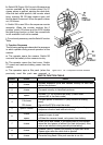
7. The lm completes its passage through the
spread rollers. The front cover idler gear meshing
with the gear train powers the top roller which
drives the lm through the exit slot.
8. The Fresnel carrier when fully scated is held by
the recock ram.
9. The pick latch releases the pick and the pick
returns to its starting position.
10. The recock ram closes S5 to cause the ECM to
shut off and dynamically brake the drive motor.
i- When power is removed from solenoid #1 (and
the shutter begins opening), the actuator on the
plunger returns switch S4 to its original condition
(CA closed); When the exposure timing cycle
is complete, power is returned to solenoid #1
and the shutter closes, opening CA, closing CB,
placing solenoid #1 again in the power down
condition and starting the motor to eject the
exposed lm.
NOTE : the lenght of, the timing cycle is
determined in amount of the light reaching the
photocell. If there is insufcient light to correctly
operate the integration circuits, the system will
automaticall terminate the exposure within 14 to
30 seconds.
taken until mirror bounce has subsided.
d- The operators closes and latches the front
cover. S7 closes, power is apllied and the camera
eject the dark slide.
NOTE : During this action (and in certain other
operations) other switches actuate and functions
occur but, unless they contribute to the paticular
camera function being described, they are
omitted from the discussion).
The counter indicates exposures #10 (and opens
S8) thereby showing that the camera is ready to
take rst picture.
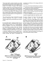
e- The operators aims, focuses the lens, and
presses the red shutter release button (S1).
The ECM actuates solenoid #1 which closes
the shutter blades. Solenoid #1 transfers the S4
contacts from CA to CB, which in turn, switches
the circuit from full solenoid power to holding
current (power-down). Closing contacts CB of
switch S4 also starts the drive motor. Opening
S4 (CA) removes power from the FFA.
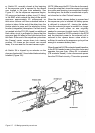
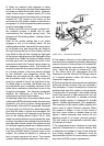
f- As the gear train runs, it mechanically releases
the spring-loaded Fresnel carrier so that it leaves
the lm plane and rises to its exposure position.
This is accomplished by the mirror release cam
of the recock gear. the recock ram falls off the
recock cam, allowing the ram to snap forward.
This allows the drive spring to raise the Fresnel
assembly to the exposure mode. The ram also
moves away from S5 allowing S5 to open. This
action causes the ECM to dynamically brake the
motor which will remain at the rest throughout the
exposure segment of the cycle. The S5 switch
action also programs the ECM to complete the
cycle even though the operator has released the
exposure button after S5 is open.
NOTE : there would appear to be a contradiction
between this step and the step j-10 below wherein
closing of S5 performs the identical function, i.e,
stops the motor and applies braking. S5 is able
to perform in this manner, however, because
the circuit (gate) to which it is connected is in a
different condition during each of the steps.
g- While the Fresnel carrier was moving up prior
to motor shutdown, the recock ram opens switch
S3. When S3 opens, it signals the ECM to initiate
a 40 millisecond delay in the sequence. This
amount of time prevents a picture from being