


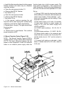
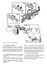

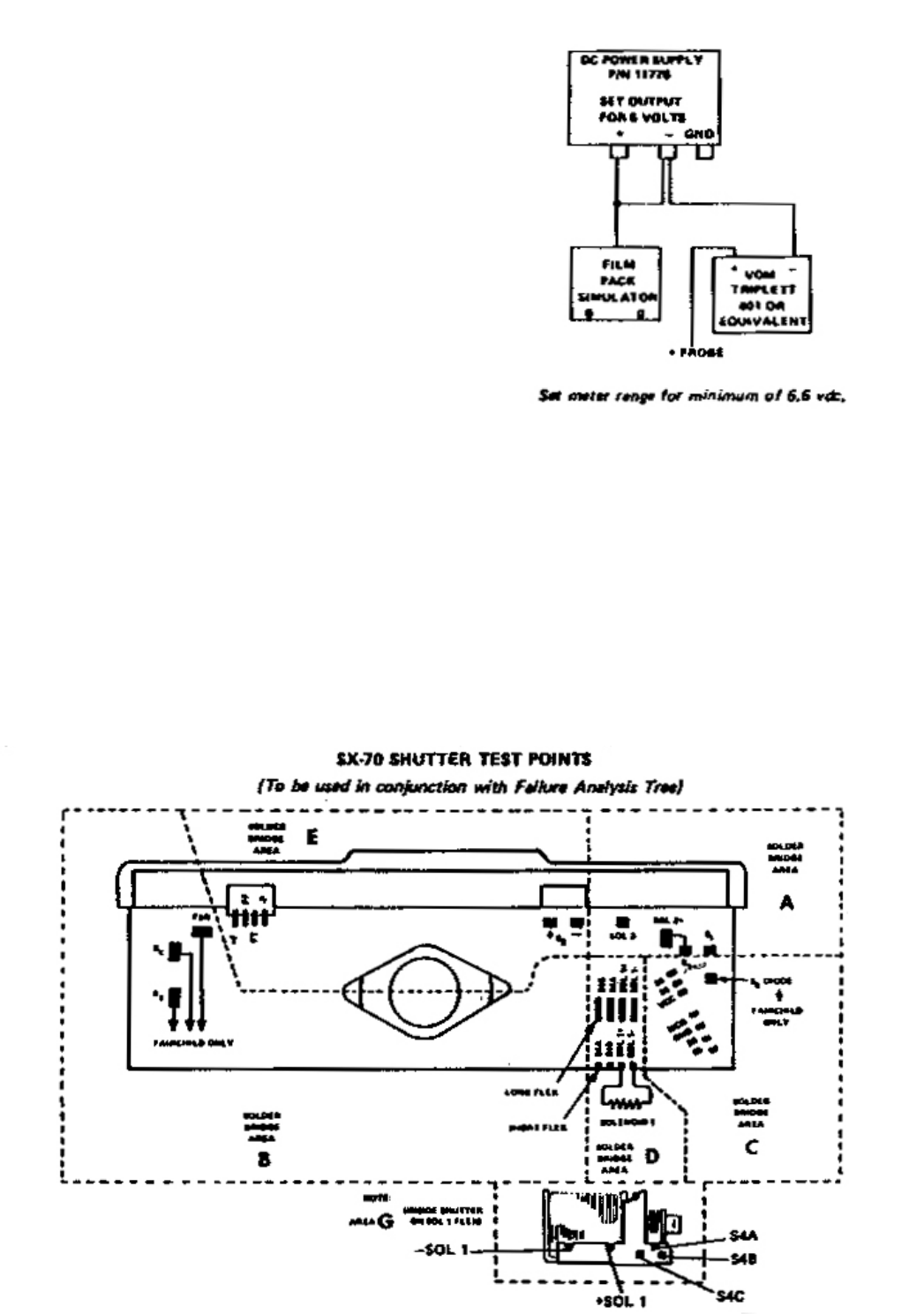
Figure 3-19 Test points on SX-70 shutters
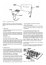
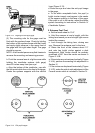
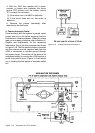
Figure 3-18 Testing instrument connections
d. With the 1000 ohm resistor still in place,
connect a jumper wire between the motor
(minus TP9 contact) and the battery (minus
TP1 contact) for a moment :
(1) If the motor runs, the MMC is defective.
(2) If the motor does not run, the motor is
defective
e. Remove the jumper immediatly after
determining the fault aera.
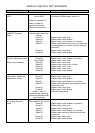
2. Camera Analysis Charts
Once familiarity with the system is gained, repair
people can rely on the failure analysis charts to
troubleshoot camera problems. When the charts
lead you to a repair procedure, refer to Section IV,
Repairs and Adjustments for the necessary
information. Set up the test equipment as shown
in Figure 3-18. The lm pack simulator is inserted
into the camera and the negative lead from the
VOM is connected to camera ground through
the power supply. This allows all the tests to be
completed simply by moving the VOM lead as a
probe from point to point. Figure 3-19 will assist
you in locating the test points or terminals called
out.