


IV - REPAIR AND ADJUSTMENTS
This section of the manual is primarily devoted
to disassembly/reassembly procedures. These
procedures provide step by step instructions
aimed at guiding the technician through
the intricacies of SX-70 camera repair. The
procedures cover such things as replacement
of improper linkages or connections, repair of
electrical malfunctions, and adjustments needed
to return the camera to proper operation.
It should be stressed that these procedures are
intented to serve as guides for the experienced
repair technician. Except where noted otherwise,
the actual repair procedure to be used is left
to the discretion of trained personnel. Their
combination of training and experience should be
sufcient to allow repair personnel to make on the
spot judgements a to the best method of repair.
A major factor which must be considered is the
trade-off between time and cost materials. If the
repair is easy and feasible from a cost viewpoint,
it should be made. Otherwise, replacement of a
part or sub-assembly is the proper choice.
There is one other general note that pertains to
SX-70 camera repair. Occasionally, screw holes
in the plastic become stripped. This is most apt to
occur in the counter mouints, the motor mounts
and where the rear upper inner frame meets the
outerplate. To make an effective repair when
this happens, replace the original screw with an
oversize screw or insert a thin sliver of plastic
into the stripped hole before the original screw
is returned.
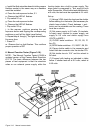
The spread rolls in the SX-70 camera are gear
driven by the main gear train. Thus, in addition
to wear or damage to the rolls, it is possible to
encounter wear and/or damage to the drive gear.
Regardless of the nature of the malfunction,
the complete assembly must be replaced. The
following paragraphs describe the replacement
procedure.
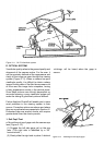
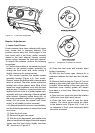
Removal
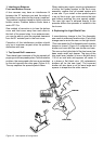
1. Erect the camera to picture taking conguration.
2. Open the front cover by depressing the front
cover release latch on the right side of the
camera bed.
3. Apply pressure to the side of the cover adjacent
to the cover hing aera. Press toward the gear
train side of the camera. This will release the
front cover. On newer models, detach the front
cover from the right side (gear train side) only.
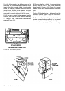
4. inspect and clean the rollers and gears with
a Q-tip moistened in water. If lm developer is
observed under the light shield or in the lm
catcher spring aera, the front cover housing
must be repaced.
5. If necessary, as described above, replace the
front cover housing and test.
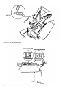
6. If the spread roll assembly is to be removed,
strip the leather from the cover. (Start pulling
the leather from the back and pull toward the
lm exit. Do not start at the lm exit.) Take out
two screws which secure the spread rollers to
the inside of the front cover, and remove the roll
assembly from the cover.
Installation
1. Position the spread roll assembly in the front
cover so that the gears will mate with the main
gear train when the cover is in place.
2. Install and tighten the two retaining screws
used to secure the rolls.
NOTE : A new se-tapping, square socket
head, coarse thread screw, PIN 705564 is
used to effect a repair of stripped thread in the
front cover assembly when installing a spread
system assembly. If the hole was stripped
during disassembly, the new screw will permit
easy reassembly. (This screw is standard on
newer cameras.)
A new square screwdriver tool bit. PIN 11867, is
available from Waltham Parts Dept.
3. Position the front cover housing on the camera.
4. Install the decorative leather covering. Make
sure the lm exit is not covered by the leather.
5. Install the front cover by squeezing the sides
of the cover just enough to engage the hinge on
the pivot points of the bottom plate.
6. Close the cover and check the camera for
proper operation.
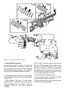
NOTE : If mishandling or dropping of the
camera causes breakage of the extruded metal
studs used to secure and pivot the front cover,
no repair is possible. Must replace the inner
camera back assembly.
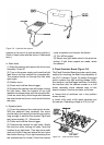
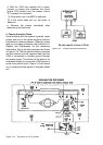
Figure 4-1 illustrated the studs mentioned.
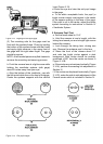
INTRODUCTION
A. FRONT COVER/SPREAD ROLL ASSEMBLY