


10
Locations and Functions of Parts
Chapter 1 Overview
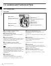
1-3 Locations and Functions of Parts
1-3-1 Camera Head
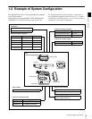
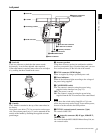
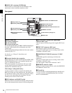
Front panel
a VF1 (viewfinder 1) connector (20-pin)
Connect a viewfinder (optional).
b CONTROL PANEL connector
Connect with the CAMERA connector of the supplied
assistant panel (page 15).
c Accessory receptacles
Using these screw holes in combination with the accessory
pockets (page 11) on the left side, you can fix a certain
accessory to the left side of the camera.
d VF2 (viewfinder 2) connector (20-pin)
Connect a second viewfinder (optional), e.g. for an
assistant.
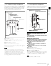
When two viewfinders are connected at the same time (via
the VF1 and VF2 connectors), if an HDVF-C950W is
connected to either connector, use an HDVF-C35W as the
other viewfinder. Because of a limitation of current
capacity, two HDVF-C950W viewfinders cannot be used
simultaneously.
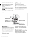
e Viewfinder shoe
Attach an optional viewfinder.
The height of the attaching position can be adjusted.
For details, see “2-4 Attaching a Viewfinder” (page 21).
f Flange focal length adjustment screw
You can adjust the flange focal length with the screw
behind the cover.
For details, see “Adjusting the flange focal length” (page
20).
g Lens fixing lever
Turn the lever clockwise to secure the lens in the lens
mount. To remove the lens, turn the lever
counterclockwise.
For details, see “2-3 Attaching a Lens” (page 20).
h Lens mount cap
Cover the lens mount with this cap when a lens is not
attached. The cover may be removed by rotating the lens
fixing lever counterclockwise.
i Shutter emergency opening screw
You can forcibly open the shutter in an emergency.
For details, see “To forcibly open the shutter” on page
109.
b CONTROL PANEL connector
c Accessory receptacles
d VF2 connector
eViewfinder shoe
Lens mount
hLens mount cap
a VF1 connector
gLens fixing lever
fFlange focal length adjustment screw
iShutter emergency open screw
Note