


14
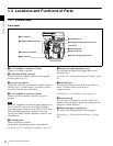
Locations and Functions of Parts
Chapter 1 Overview
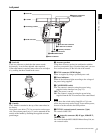
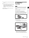
f MENU SEL (selection) /ENTER dial
Used to select or set the items on the subdisplay or the
menu items on the viewfinder (monitor) screen.
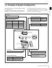
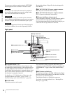
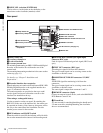
Rear panel
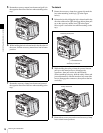
a Safety release tab
b Accessory clamp lever
c Lock release knob
d Accessory mount lever
For mounting/unmounting an SRW-1 HD Portable Digital
Recorder or the interface box to/from the rear of the
camera head.
The mounting/unmounting mechanism is the same as that
on the top (page 13).
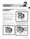
For details, see “Chapter 2 Installation and
Preparations”.
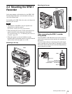
e Recorder/interface box receptacles
Signals and power are sent/received to/from an SRW-1 HD
Portable Digital Recorder or the supplied interface box
(page 15) mounted on the rear.
The same receptacles are provided on the top to send/
receive signals and power to/from the recorder or the
interface box mounted on the top.
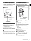
When using a rechargeable battery
Use the receptacles on the rear panel. By attaching the
BKP-L551 to the rear of the interface box, the camera can
be operated on a battery. Note, however, that power will be
fed only to the camera head and viewfinder. Provide
another power source for the recorder.
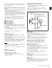
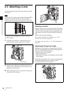
f RUN indicator and ON/OFF switch
When the switch is set to ON, the indicator will be lit while
the recorder mounted on the camera is in Recording mode.
g GENLOCK IN (external sync signal input)
connector (BNC type)
Used for input of an external gen-lock signal (HD 3-level
sync).
h TEST OUT connector (BNC type)
An analog test signal is fed from the connector.
The type of output signal can be set using a menu on the
viewfinder or monitor screen.
i MONITOR OUT HD SDI connectors 1/2 (BNC
type)
An HD SDI signal for monitoring is fed from the
connectors.
The type of output signal can be set using a menu on the
viewfinder or monitor screen.
The same signal is output from connector 1 and 2.
j REMOTE connector (8-pin)
Connect an external control device, such as the RM-B150/
B750 Remote Control Unit.
k Wrench box
A 3-mm wrench for attaching/detaching the handle and a
2.5-mm wrench for attaching/detaching the viewfinder
shoe are accommodated.
OFF ON
REMOTE
23
fRUN indicator and ON/OFF switch
gGENLOCK IN connector
hTEST OUT connector
iMONITOR OUT HD SDI connectors 1/2
DC IN connector (see page 11)
e Recorder/interface box
receptacles
jREMOTE connector
b Accessory clamp lever
c Lock release knob
kWrench box
a Safety release tab
d Accessory mount lever