


34
Basic Settings with the Subdisplay
Chapter 3 Basic Adjustments and Settings
• If a gamma other than S-LOG is selected
The upper limit is clipped according to the output video
limitation specified by the gamma setting.
When you select a curve as Hyper Gamma No. 4, which
compresses 460% input to 109%, the output video is fed
within the range up to 460% of input video even if 800%
is displayed on the subdisplay as the dynamic range as the
output video is limited to 109%.
Using CvpFileEditor V4.0, you can change the dynamic
range of Hyper Gamma and create a user gamma curve
having no dynamic range limitation.
• If the white clip function is in use
As the white clip function limits the level of output video,
the dynamic range specified for the input video may not be
obtained for video output.
• If “Select FPS” is ON and Compensation is in Gain
mode
The value of the dynamic range may decrease by up to half
at maximum, depending on the FPS settings.
Why the ISO sensitivity is defined for 20% input
Defining the level of gray scale of 18% reflection rate for
the ISO sensitivity on the linear curve (defining with input
signal) permits you to use the values as the absolute
reference for proper gamma conversion in postproduction.
In addition, defining the output for 20% input with ITU-
R709 so that it becomes the reference code for Cineon
curve allows high compatibility.
3-2-6 Selection of a Lens File
With this camera, the compensation data for the mounted
lens can be adjusted in Custom mode and registered in the
built-in memory in lens files (max. 32 files).
You can invoke the compensation data for the mounted
lens by merely selecting the corresponding file.
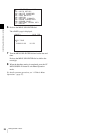
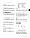
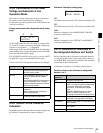
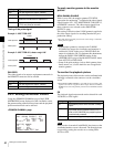
Lens file selection page
On the first line, select the number of the lens file.
On the second line, the lens-file name corresponding to the
selected file is displayed.
The selected lens file will be retained until a new lens file
is selected. As long as the same lens is used, further
selection of the lens file is not required.
All the lens files are named “No Offset,” with all zero
settings at shipment. File registration and modification of
data in a lens file must be performed in Custom mode.
For details on the lens files, see “Chapter 5 Storage and
Retrieval of User Setting Data”.
3-2-7 Confirmation of the Time Code
and Tape Remaining
When the SRW-1 HD Portable Digital Recorder is attached
to this camera, the time code of the recorder and
approximate tape remaining (unit: minutes) can be
confirmed on the subdisplay.
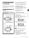
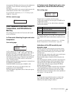
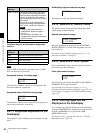
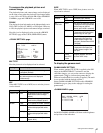
Time code/tape remaining display page
The time code is displayed on the first line, and the
approximate tape remaining is displayed on the second
line, in the range of 1 to 99 min.
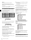
Time code that is displayed on the first line
The type of the displayed time code data is linked with the
SRW-1. Select the type of the displayed time code data on
the SRW-1.
Memo
LENS:1
No Offset
Note
Indication Meaning
TCR 00:00:00:00 Time code data of the LTC reader
TCR 00:00.00:00 Time code data of the LTC reader (DF)
TCR.00:00:00:00 Time code data of the VITC reader
UBR 00 00 00 00 User bit data of the LTC reader
UBR.00 00 00 00 User bit data of the VITC reader
TCG 00:00:00:00 Time code data of the time code
generator
TCG 00:00:00.00 Time code data of the time code
generator (DF)
UBG 00 00 00 00 User bit data of the time code
generator
CTL -0:00:00:00 Data of the CTL counter
T*R 00:00:00:00 Time code cannot be read with the
LTC reader.
U*R 00 00 00 00 User bit cannot be read with the LTC
reader.
T*R.00:00:00:00 Time code cannot be read with the
VITC reader.
U*R.00 00 00 00 User bit cannot be read with the VITC
reader.
TCR 00:00:00:00
20min