


9
Example of System Configuration
Chapter 1 Overview
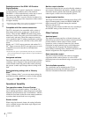
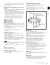
1-2 Example of System Configuration
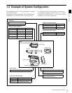
The diagram below shows a system configuration example
to use of this camera.
In this manual, an optional HDVF-C35W HD Electronic
Viewfinder is used to instruct how to operate the unit.
For more information about the fittings, connections, or
use of additional equipment and accessories, see “Chapter
2 Installation and Preparations” as well as the operation
manuals for the connected equipment.
Viewfinder-related equipment
Name / Purpose Magnification Part No.
Fog-proof filter — 1-547-341-11
Lens assembly –2.8 D to +2.0 D A-8262-537-A
Lens assembly –3.6 D to –0.8 D A-8262-538-A
Lens assembly –3.6 D to +0.4 D A-8267-737-A
Lens assembly
(3 × magnification)
–2.4 D to +0.5 D A-8314-798-A
L
O
C
K
Video recorder
SRW-1 HD Portable Digital Recorder
Remote control devices
RM-B750 Remote Control Unit
MSU-900/950 Master Setup Unit
Data storage media
“Memory Stick PRO”
“Memory Stick PRO Duo”
Products for tripod mounting
Name Model name
Bridge Plate BP-5 (ARRIFLEX made)
Shoulder Set S-1 (ARRIFLEX made)
F35
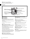
Product Configuration
Center handle
L handle
Assistant panel
Interface box
Camera head
Viewfinders
HDVF-20A HD Electronic Viewfinder
HDVF-C35W HD Electronic Viewfinder
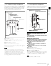
Products for battery operation
Product for AC power supply
Product Model name
Rechargeable Battery Pack BP-GL95
Battery Adaptor BKP-L551
Product Model name
AC Adaptor AC-DN2B
Riser plate