


11
Locations and Functions of Parts
Chapter 1 Overview
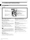
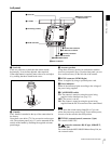
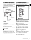
Left panel
a Level vial
Used as a reference to check that the camera stands
horizontally. It can be fine-adjusted when required.
If fine-adjustment is required, remove the cover and adjust
it by rotating the three slotted-head screws.
b L handle
The L handle is attached to the top of the camera head at
the factory.
It has three screw holes (
3
/
8
") for accessories on the upper
side. The assistant panel (page 15) can be mounted on the
outside of the handle by attaching the supplied assistant
panel hanger.
c Accessory pockets
Using these accessory pockets in combination with the
accessory receptacles (page 10) on the front panel, you can
fix a certain accessory to the left side of the camera.
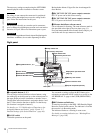
d DC IN connector (LEMO 8-pin)
Power is supplied by using a specified power cord.
e Power indicators
Either of the indicators lights according to the voltage of
the power being supplied.
f CAM POWER switch
CA: The camera is turned on using the power being
supplied via the interface box (page 15).
OFF: The power is cut off.
ON: The camera is turned on using the power being
supplied from the DC IN connector of the camera head.
If you move the switch setting from ON to CA in one
stroke, the power may not be cut off. To turn off the power,
be sure to set the switch to the OFF position.
g EXT I/O (external control) connector (5-pin)
For control via RS-232C.
h (network) connector (RJ-45 type, 10BASE-T,
100BASE-TX)
For control from the MSU-900/950 Master Setup Unit, etc.
via a network cable.
c Accessory pockets
d DC IN connector
ePower indicators
f CAM POWER switch
g EXT I/O connector
h (network) connector
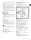
iDC OUT 12V connector
j DC OUT 24V connector
b L handle
a Level vial
k Measure hook/focus
reference mark
Note