


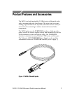
Product Features and Accessories
P6330 3.5 GHz Differential Probe Instructi on Manual
5
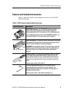
Table 1: P6330 features and standard accessori es (Cont.)
Feature/Accessory Description
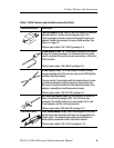
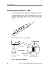
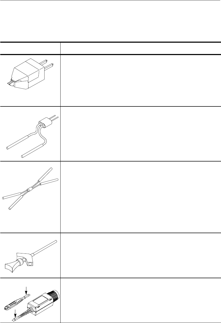
TwinFoot adapter (4 ea). Use the TwinFoot adapter to probe two
adjacent leads on a surface-mount integrated circuit. The
TwinFoot adapter connects to the probe through the square pin
adapter. Flexible fingers adapt to a range of lead spacings. See
Figure 4 on page 12.
Tektronix part number: 016-1785-00 (package of 4)
Y-lead adapter (2 ea). The Y-lead adapter connects to the probe
through the square pin adapter. The socketed ends of the leads
may be connected to the probe tips and accessories, or fitted onto
0.025-inch pins.
Tektronix part number: 196-3468-00 (package of 2)
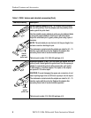
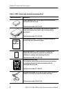
X-lead adapter (2 ea). The X-lead adapter connects between
accessories fitted with 0.025-inch pins, such as the SMT KlipChip
and Micro KlipChip adapters.
You can use the X-lead adapter with the adapters below to make
connections between the probe tip and your circuit under test.
Be aware of the electrical effects of the added lead length of the
adapters, especially as circuit frequencies increase.
Tektronix part number: 196-3473-XX (package of 1)
SMT KlipChip adapter (2 ea). Use this accessory to probe the
leads on dual-in-line packages (DIP). The 0.025-inch pins
recessed in the adapter body may be connected to the X- and
Y-lead adapters, and the 3-inch ground leads.
Tektronix part number: 206-0364-XX (package of 1)
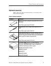
Color marker bands
Color marker bands (10 ea). Attach matching pairs of the color
marker bands onto the cable at the head and compensation box
of each probe. The marker bands enable quick verification of
which probe is connected to which instrument channel.
Tektronix part number: 016-1315-00 (package of 10)