


Performance Verification
P6330 3.5 GHz Differential Probe Instructi on Manual
41
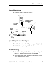
Output Offset Voltage
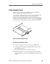
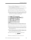
1. Connect the probe as shown in Figure 18.
1103
CH 1
input
CH 1
output
Digital multimeter
Female BNC-to-male
banana adapter
50 Ω precision
terminator
50 Ω BNC cable
Square pin
adapter
Y-lead
adapter
KlipChip
adapters
Figure 18: Setup for the output offset voltage test
2. Set the Var/0v button on the 1103 power supply to 0v (l ight off).
3. Verify that the output voltage is 0 V,
±10 mV.
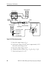
DC Gain Accuracy
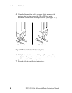
1. Connect the probe input to the DC source, as shown in Figure 19
on page 42. Monitor the source voltage with the DMM.
2. Set the input voltage on the DC source to approximately +0.5 V.
Record the actual voltage as V
in
1.