


Operating Basics
10
P6330 3.5 GHz Differential Probe Instruction Manual
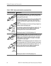
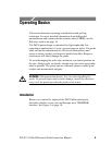
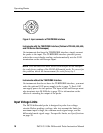
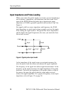
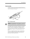
Figure 2: Input connector of TEKPROBE interface
Instruments with the TEKPROBE Interface (Tektronix TDS 400, 500, 600,
and 700 Series Oscilloscopes)
On instruments that have the TEKPROBE interface, simply connect
the probe to the input. The TEKPROBE interface provides power,
selects the correct display scaling, and automatically sets the 50 Ω
termination on the oscilloscope i nput.
NOTE. TDS 400 and TDS 400A serie s oscilloscopes do not interpret
the scale factor coding of the P6330 differential probe. To correct for
this problem, divide the measurement (or scale factor) by 5.
Instruments without the TEKPROBE Interface
On instruments that do not have the TEKPROBE interface, you must
order the optional 1103 power supply (refer to page 7). Each 1103
can supply power for two probes. The input of the osc illoscope must
also terminate into 50 Ω. Refer to page 22 for information on the
effects of extending the output of the probe.
Input Voltage Limits
The P6330 differential probe is designed to probe low-voltage
circuits. Before probing a voltage, take into account the limits for
maximum input voltage, the common-mode signal ra nge, and the
differential-mode signal range. For specific limits, see Specifications
on page 25.