


Reference
P6330 3.5 GHz Differential Probe Instructi on Manual
21
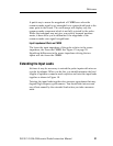
A quick way to assess the magnitude of CMRR error when the
common-mode signal is not sinusoidal is to connect both leads to the
same point in the circuit. The oscilloscope will display only the
common-mode component which is not fully rejected by the probe.
While this technique may not give you entirely accurate measure-
ments, it does allow you to determine if the magnitude of the
common-mode error signal is significant.
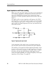
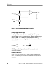
Input Impedance Effects on CMRR
The lower the input impedance of the probe relative to the source
impedance,thelowertheCMRR.SeeFigure12onpage28.
Significant differences in the source impedance driving the two
inputs will also lower the CMRR.
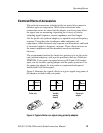
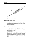
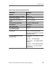
Extending the Input Leads
At times it may be necessary to extend the probe inputs with wires or
a probe tip adapter. When you do this, you should minimize the lead
lengths to optimize common-mode rejection and twist the input leads
together as shown in Figure 10.
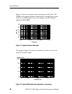
Twisting the input leads together does increase capacitance that may
degrade high-frequency performance. You should take into account
any effects caused by the extended leads when you take a measure-
ment.