


P6330 3.5 GHz Differential Probe Instructi on Manual
33
Theory of Operation
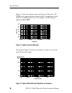
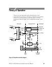
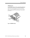
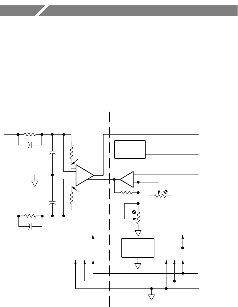
There are no user replaceable parts within the probe or the
compensation box; however, this theory of operation is provided to
assist you in isolating failures to either the probe or the host
oscilloscope. Refer to Figure 14 for a simplified schematic of the
probe.
Offset
Gain
Offset
Zero
Offset Ampifier
EEPROM
Probe Tip
Ampifier
Signal Out
Probe Tip
±1VOffset
Probe ID Out
+5 V
-- 5 V
Ground
Probe
Cable
TEKPROBE
Interface
Probe Head Compensation Box Oscilloscope
Clock In
+--
Probe Tip
+15 V
Linear
regulator
+7 V
IN +
IN --
+
--
in
-- offset
+offset
Figure 14: Simplified schematic di agram