


Operating Basics
P6330 3.5 GHz Differential Probe Instructi on Manual
15
Probe Grounding
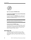
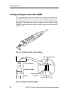
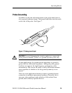
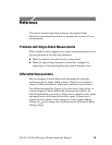
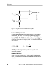
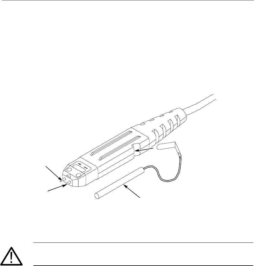
In addition to the plus and minus inputs on the probe head, there is
also a ground (common) input. The ground lead slides into the notch
on the side of the probe. See Figure 7.
+
--
Ground
Figure 7: Probe ground input
CAUTION. To avoid damaging the circuitry under test, connect the
probe ground (common), if used, to a ground-reference point only.
In most applications, the common-mode impe dance to ground is
greater than the differential impedance. Adding the probe ground
lead does not improve the high-frequency performance of the
measurement. You can use the probe to take a differential measure-
ment regardless of whether or not the ground (common) is con-
nected.
There are some applications that may require a ground reference
connection to maintain measurement accuracy. Generally this is
necessary when probing circuits which are fully isolated from
ground, such as battery operated devices.