


2 © 2008 VBrick Systems, Inc.
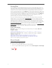
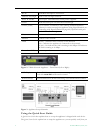
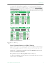
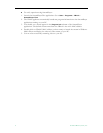
Figure 2. VBrick Network Appliance – Front Panel (Left to Right)
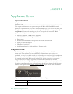
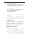
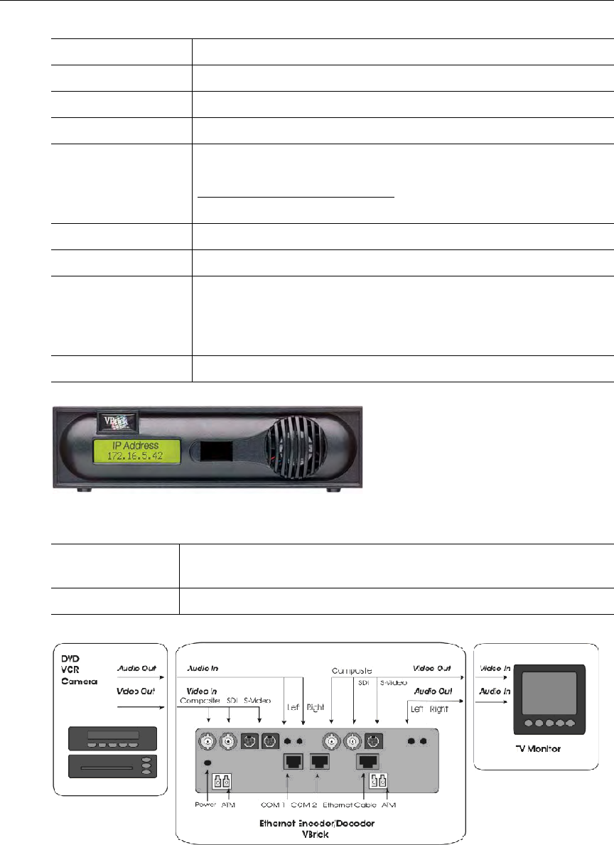
Figure 3. Appliance Setup Schematic
Using the Quick Start Guide
A Quick Start Guide that explains how to set up the appliance is shipped with each device.
The Quick Start Guides explain how to setup the appliance so you can quickly verify that you
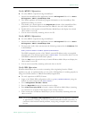
Mic In AudioMate microphone connection.
Audio In Left/Right Audio in left and right channels.
Power In 24VDC Power input. LED illuminates when power is applied.
COM 1 Dedicated serial port for Serial Port Passthrough.
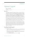
COM 2 (Term) Use to connect a terminal (or a PC running terminal emulation
software) in order to manage the appliance using HyperTerminal (see
Connecting with HyperTerminal
on page 49). Optional serial port
for Serial Port Passthrough.
Relay Use to control external devices.
Ethernet Connect to the network.
LEDs Activity – indicates there is activity on the network.
Link – indicates the appliance is connected to the network.
10/100 – On indicates the link is running at 100 Mbps. Off indicates
the link is running at 10 Mbps.
Power Out 12VDC Power output. Connect external devices such as a camera.
LCD Display Shows IP Address, system status, error messages, and Edit state. Also
used with
Local Edit on IR remote control.
Infrared Sensor Located between LCD and fan housing. Used for IR remote control.