


MIC400 Series Camera | Installation and Operation Manual AAAEN | 14
Bosch Security Systems Issue 1
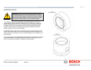
Electrical Connections
A purpose built composite cable for use with the camera is available; these cables
are pre-made with a Female terminated 12 way connector fitted to them for
attachment to the Male connector installed into the base of the camera.
The composite cable has no termination (free wires) at the other end for wiring into
the appropriate power supply. The standard colour coding used in these cables is
as shown below.
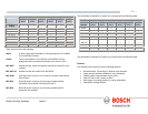
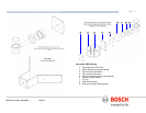
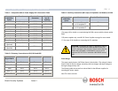
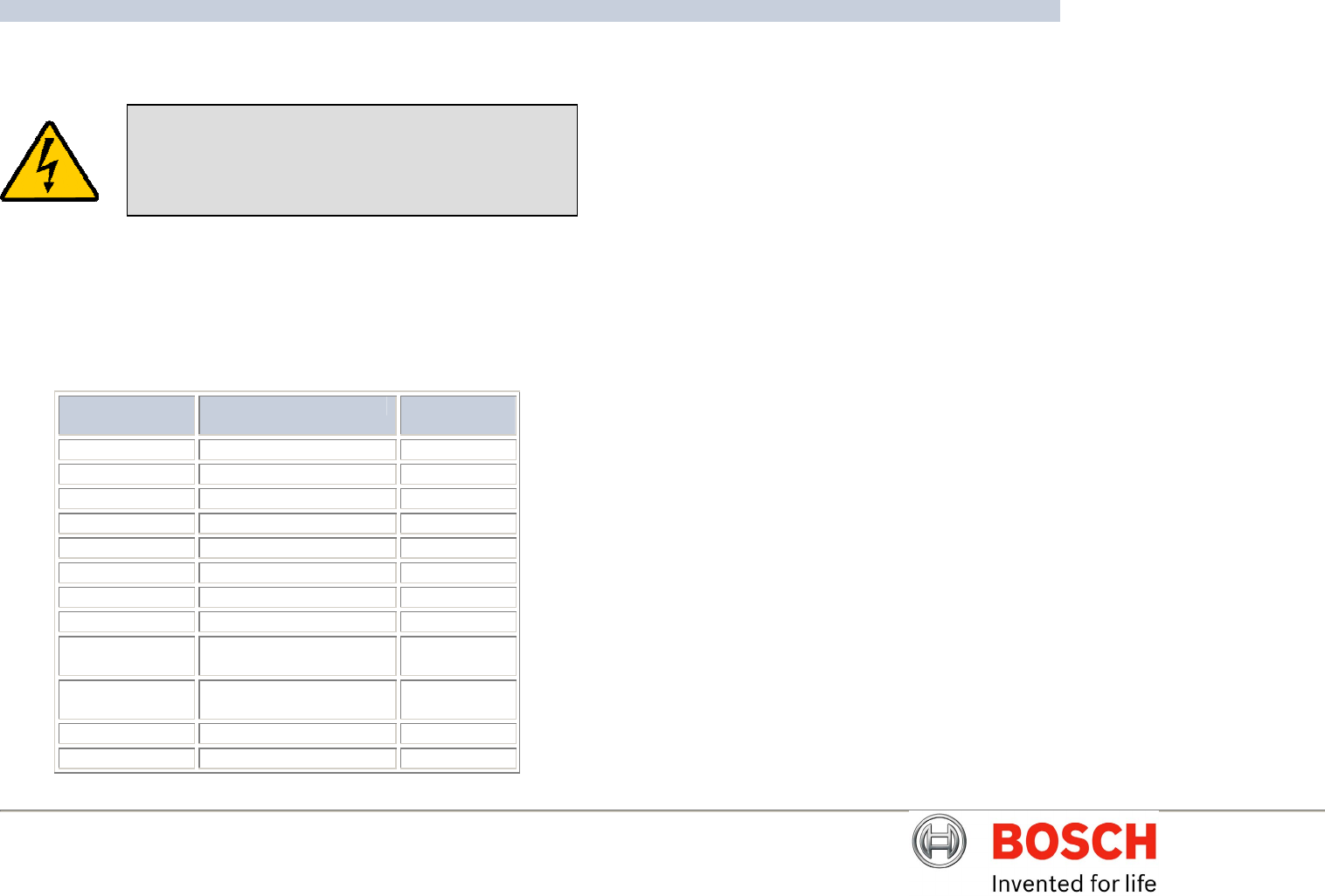
Table A – MIC Composite Cable Pin table
MIC400
Connector Pin
Signal Name Cable Wire
Colour
A Video Output Coax core
B Video Return Coax screen
C Tamper Sw Black
D Tamper Sw Rtn Brown
E Washer drive Rtn Grey
F Washer drive Orange
G Full Duplex Tx A. Blue
H Full Duplex Tx B. Violet
J Full Duplex Rx A.
Half Duplex Tx/Rx A.
Yellow
K Full Duplex Rx B.
Half Duplex Tx/Rx B.
White
L Power input 1. Red
M Power input 2. Green
CHAPTER 3 Power Supply Installation & Setup
The Power Supply Units provide all the support functions for connecting the
MIC400 cameras to third party equipment, they comprise of:
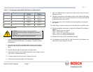
NON-IR Power Supply Units
MIC-240PSU, MIC-24PSU and MIC-115 PSU
The power supply provides power for a single MIC400 non-ir camera unit from
either a 240v AC source (MIC-240PSU), a 24v AC (MIC-024PSU) or a 115v AC
source (MIC-115PSU). The transformer fitted to these designs is a thermally
protected transformer that automatically cuts out if the transformer core
temperature exceeds 40 Degrees C. On cooling the transformer will become
operational again.
In addition the unit provides all the terminations required to connect a MIC400
camera to third party equipment.
A second independent 12v (600mA) power supply is also included to drive any
internally fitted optional interface cards.
Dimensions
Power supply enclosure:-225mm (W) x 70mm (H) x 195mm (D)
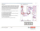
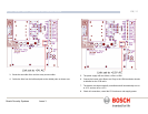
The Power Supply Unit provides all the support functions for connecting the
camera to third party equipment. It comprises of:
1) A weather resistant (IP55) plastic box fitted with four cable glands.
2) A power supply for the MIC400 camera.
3) A second power supply for driving various interface cards mounted internally
to the power supply box. e.g. washer drive card, alarm interface card.
4) Provision for a signal interface card, to connect telemetry to third party
equipment.
5) Screw termination of all cable into and out of the box.
6) Correct video termination for the camera coaxial cable.
7) Earth isolation and termination within the unit to correctly control Video
earthing and thus prevent Earth loop.
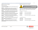
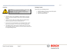
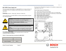
WARNING: Electrical Danger: Ensure all power is
disconnected before opening or working upon the Power
Supply Unit.
Installation must be carried out by suitably qualified
persons.