


MIC400 Series Camera | Installation and Operation Manual AAAEN | 24
Bosch Security Systems Issue 1
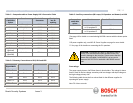
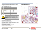
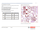
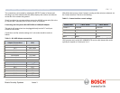
10. A washer drive is provided on this power supply, a mains rated relay is
fitted and pre-wired to the mains input feed via an on board fuse FS4
(rated at 2 Amps Ceramic quick blow) connection to a third party washer
pump system should be made via HD7 as per Table K.
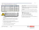
11. Once connected the washer drive can be tested using the red SW1 which
should activate the pump. This will allow for priming the plumbing. When
pressed the LED, (LED3) next to the washer switch should illuminate. The
LED will also illuminate in response to telemetry commands to switch the
washer on
. The Red LED on the washer PCB will illuminate when the
Washer function is selected at the control room end. Note that the
software in the camera prevents the washer from being run more than 10
seconds continuously. (This is to prevent the washer bottle from being
inadvertently emptied. The red button on the washer drive card can be
used to both test the washer operation and to prime the washer pump.
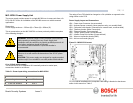
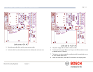
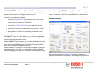
12. When wiring is complete, apply power & check the all six (6) LED’s are lit.
LED1 and LED2 when light show that 15v AC is available from the power
supply (i.e. the supply fuses are intact. There is no indication of the
operation of the Telemetry lines as this would increase the load on these
lines reducing the number of cameras that can be driven by a single
telemetry spur.
LED 3 illuminates when the washer drive relay is selected to on.
LED 4 monitors the internally generated +5v rail used to drive the alarm
interface circuits around HD2. This +5v supply is not available externally.
LED 5 illuminates when the IR supply is selected to on by the camera
telemetry.
LED 6 Pulses on/off when the MIC400 camera is correctly configured to
operate with the IR power supply.
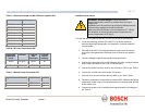
13. When satisfied the PSU is functioning correctly, re-attach the enclosure lid
& screw down until tight.
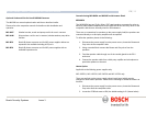
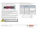
MIC-IR-12PSU
The power supply operates from a 12v DC source typically between 10.5v and 15v
DC, for example, a lead acid battery. The PSU provides power to a MIC400
camera at 18v DC nominally.
Current draw:
For the camera non-moving is 600mA. Worst-case current draw whilst moving is
1.5Amps
Max current draw with camera moving, wiper on and IR illuminators on is 3.8Amps.
Dimensions
Power supply enclosure: - 260mm (W) x 90mm (H) x 120 (D)
A weather resistant (IP66) box prefitted with four cable glands.
A second isolated power supply for driving the IR illuminators, the operation of this
power supply is controlled by the camera itself via telemetry commands received
from the control room. The power supply operates with dual illuminators. This drive
is a constant current drive which automatically configures itself for IR lamp
operation. There are no adjustable items within the power supply except for the
three links discussed below.
Screw termination of all third party cables into and out of the box.
Correct video termination for the camera coaxial cable.
The power supply provides a circuit for operating a 12v driven washer drive pump
and reservoir system.
The power supply also supports 4 off volt free alarm contact inputs, which can be
made to activate presets within the camera but always notifies the control system
of the status of these alarms.
Earthing; the power supply and all equipment connected to it is earthed to the –ve
side of the battery supply permanently.