


MIC400 Series Camera | Installation and Operation Manual AAAEN | 16
Bosch Security Systems Issue 1
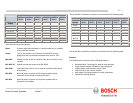
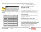
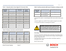
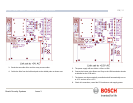
Table C - Composite cable to Power Supply HD-3 Connection Table
Composite
Cable Wire
Colour
Function Terminal Box
Connector
Terminal
box ID
marking
Red AC supply HD3-1 Power
Green AC supply rtn. HD3-2 Power
White Rx + HD3-3 RxB
Yellow Rx - HD3-4 RxA
Drain Wire Gnd HD3-5 GND
Blue Tx - HD3-6 TxA
Violet Tx + HD3-7 TxB
Coax Core Video HD3-8 Video
Coax Screen Video Return HD3-9 Vid 0v
Black
(Optional)
Tamper Switch HD3-10 Tamp Sw
Orange
(Optional)
Wash drive HD3-11 Wash
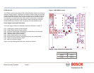
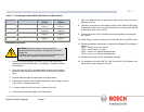
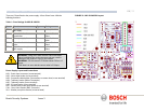
Table D –Telemetry Connections to HD3, HD4 and HD5
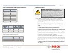
Table E –Auxiliary connections (IR Lamps, PA Speakers and Heaters) to HD6
*See page 19 for details on commissioning MIC400 cameras with the heater option
fitted.
**IR power supplies only, see MIC-IR Power Supplies on page for more details.
*** See page 19 for details on connecting the PA speakers.
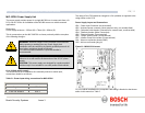
Fuse ratings
The power supply houses 4 off 20mm fuses in fuse holders. The ratings for these
fuses if fixed on the low voltage secondary side but changes with input voltage on
the high voltage primary side.
The following table shows the fuse values fitted for the different supplies for
operating the power supply:
Note FS 4 does not exist
Telemetry
Signal Name
HD3 HD4 HD5
RXB or Rx + Pin 3 Pin 1 Pin 1
RXA or Rx - Pin 4 Pin 2 Pin 2
GND Pin 5 Pin 3 Pin 3
TXA or Tx - Pin 6 Pin 4 Pin 4
TXB or Tx + Pin 7 Pin 5 Pin 5
Composite
cable Wire
colour
Function Terminal Box Connector
Brown Heater* or IR Lamps**
or PA speakers***
HD6-1
Grey Heater* or IR Lamps**
or PA speakers***
HD6-2
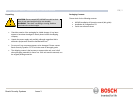
CAUTION: Connecting MIC400IR or MIC400PA units to
a MIC-PSU with the heater option enabled as this can
result in damage to the cameras. Please ensure that the
heater link is disabled if a MIC400PA is to be used or
ensure a MIC-IR-PSU is used with a MIC400IR camera
unit.