


MIC400 Series Camera | Installation and Operation Manual AAAEN | 27
Bosch Security Systems Issue 1
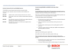
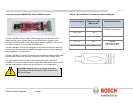
16. LED 5 illuminates when the IR supply is selected to on by the camera
telemetry.
17. LED 6 Pulses on/off when the MIC400 camera is correctly configured to
operate with the IR power supply.
18. Please see the section on commissioning MIC400 Power Supplies for
details on commissioning and setting up alarms.
19. When satisfied the PSU is functioning correctly, re-attach the enclosure lid
& screw down until tight.
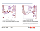
Commissioning the IR lamps
The following instructions apply to all MIC400IR cameras; please connect to a PC
via RS422/485 telemetry and Universal Camset as shown on the next page, before
applying power to the power supply check that all connections are correct.
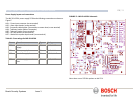
Apply power to the unit and ensure that the 2 Red LEDs at the top of the PCB
(under R1) and the +5v LED (LED4) are all on. This confirms that Fuses FS1, 2, 3,
and 5 are intact.
Check that the MIC400 is generating a video picture.
Once connected set the camera current address in CamSet and check that the
camera can be moved using the pan, tilt and stop buttons.
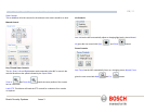
The IR lamps selection is enabled by entering the Setups tab and setting the Multi
Alarm mode on and Auto IR on. The PSU board LED should start flashing (LED 6)
called PIC OK to indicate correct operation.
CHAPTER 4
Configuring the MIC400 Camera
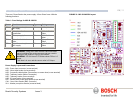
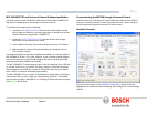
Connecting the MIC400 to the PC
The MIC can be connected to a PC’s serial port via a RS232/RS422 adaptor unit;
this will generally be assigned to Comm Port 1.
Suitable serial port adaptor units are the Greenwich RS232/RS422 adaptor unit
(Farnell 778-758, RS No: 201-758), the KK systems K2-ADE RS232 to RS485/422
adaptor or the MIC-USB485CVTR (485 to USB Converter) for PC’s without a serial
port.
Connecting the Greenwich Adaptor
To connect the Greenwich serial adaptor to the PC you will also need a 9 pin D
female to 25 pin D male RS232 compatible adaptor cable. A suitable cable is
Farnell 960-573 or RS Part No: 202-644.
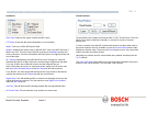
The adaptor should be set to DCE mode and the power supply connected.
Connections from the Greenwich adaptor to the MIC400 power supply are as
follows:
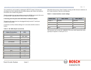
Table N – Connecting the Greenwich Adaptor
Adaptor Connections HD4
F 778-758.
Connection and wire
colour.
DATA OUT 6-3+ RXB White
DATA OUT 5-4- RXA Yellow
SCREEN 0v
DATA IN 4-5- TXA Blue
DATA IN 3-6+ TXB Violet