


MIC400 Series Camera | Installation and Operation Manual AAAEN | 28
Bosch Security Systems Issue 1
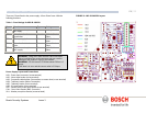
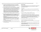
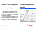
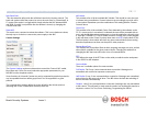
The connections can be tested by selecting the DETECT button in Camset and
checking to see if the window below this button displays the address and software
version No of the camera being tested.
Should a problem be encountered then connect the MIC400 screen wire (0v) to the
pc chassis with a separate piece of wire to ensure 0v continuity
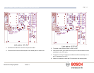
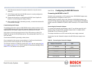
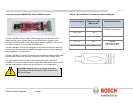
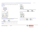
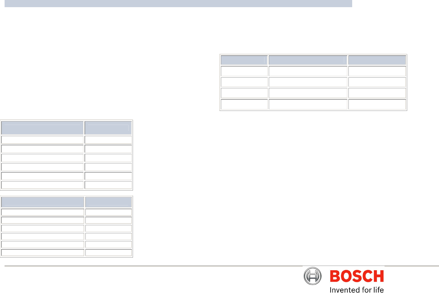
Connecting the KK systems K2-ADE RS232 to RS485/422 Adaptor
This unit is self powered and can be plugged directly into the PC serial port.
RS485 two wire mode.
Connections and Dip switches settings for 2-wire mode should be made as
follows:-
Table O – K2-ADE Adaptor connections
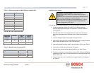
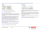
With all the above set up, when Camset is running and the serial port selected, set
the Camera Interface Controls to the following:-
Table P – Camera interface control settings
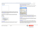
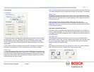
If a notebook PC is used, which sometimes lacks a serial port, then a RS485 to
USB converter such as the MIC-USB485CVTR can be used instead, this would
typically be mapped to Comms port 3 or 4.
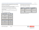
Camset Tabs 2 Wire RS485 4 Wire RS422
Comms 1 Selected Selected
Interface 2 Wire 4 Wire
RTS Off On
Baud 9600 9600
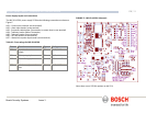
Adaptor Connections HD4
K2-ADE Connection.
Pin 3 RXB White
Pin 9 RXA Yellow
Pin 5 0v
Not required TXA Blue
Not required TXB Violet
DIP Switch Setting
Sw 1 OFF
Sw 2 OFF
Sw 3 OFF
Sw 4 ON
Sw 5 OFF
Sw 6 ON