


MIC400 Series Camera | Installation and Operation Manual AAAEN | 25
Bosch Security Systems Issue 1
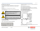
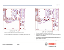
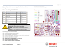
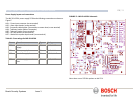
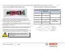
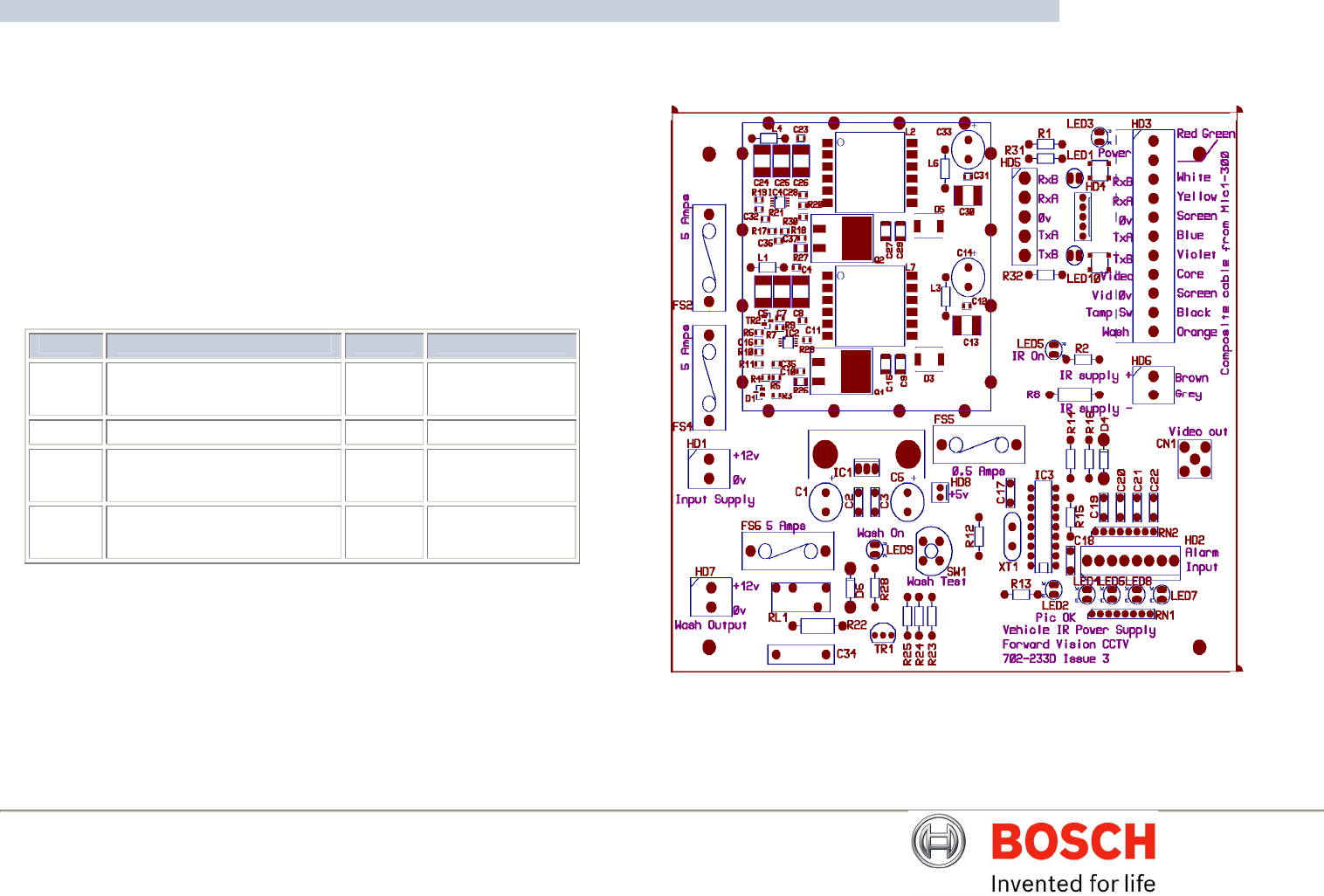
Power Supply layout and connections
The MIC-IR-12PSU power supply PCB has the following connections as shown on
Figure E
HD1 – Power Input connector (screw terminal)
HD2 – Alarm Input header (screw terminal)
HD3 - Composite cable header (Connections to camera head, screw terminal)
HD4 - Telemetry header (Molex Connection)
HD5 - Telemetry header (screw terminal)
HD6 – IR Lamp header (screw terminal)
HD7 – Washer drive power input header (screw terminal)
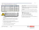
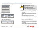
Table M – Fuse ratings for MIC-IR-12PSU
Fuse Function Type Rating
FS2 Input fuse for main camera
supply.
Glass 5A Quick Blow
FS4 IR Lamp supply fuse. Glass 5A Quick blow.
FS5 Local +5v supply fuse Glass 0.5A Quick Blow.
FS6 Washer supply protection
fuse.
Glass 5A Quick Blow.
FIGURE E – MIC-IR-12PSU Schematic
Note: there are no PCB link options on this PSU.