


MIC400 Series Camera | Installation and Operation Manual AAAEN | 15
Bosch Security Systems Issue 1
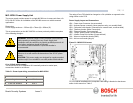
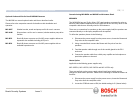
PCB Earth Link
The PCB has one link option next to HD1 to allow the power supply to be set up for
different earthing schemes: The Earth Link should be broken if there is a separate
connection between video screen and earth. Usually occurs on copper connected
systems where all the copper video coaxes are taken back to the control room to
be connected to a central earth point. If fibre optics or other indirect connections
are used to get data and video to and from the control room then the earth link
should be left intact provided it is the only camera end earth reference point.
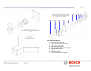
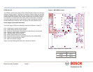
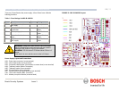
Power Supply Layout and Connections
The Power supply PCB has the following connections as shown on Figure A:-
HD1 – Power Input Connector (screw terminal)
HD2 - Tamper Switch header (screw terminal)
HD3 - Composite cable header (Connections to camera head, screw terminal)
HD4 - Telemetry header (Molex Connection)
HD5 - Telemetry header (screw terminal)
HD6 - Washer pump header (screw terminal)
HD8 - Keyboard power connector (demo purposes only, not normally fitted)
CN1 - Video out connection header (BNC)
CN2 - Add on card header (plug in)
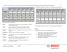
Figure A and the following tables show the connections required.
Figure A - MIC-240PSU Layout
Table B – Power Connection to Header HD1
Live HD1-1
Neutral HD1-2
Earth HD1-3